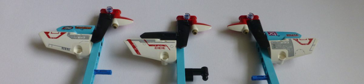
So, for the past few weeks I’ve been working on my build of the EV3DPrinter. I’ve had it printing various geometric shapes, “College” letters, and more recently I’ve been working on a complex shape – namely a castle:

Development
Since I’ve been programming my instance of the EV3DPrinter in EV3G I couldn’t realistically use G-Code as the string handling in EV3G isn’t up to the task. Instead I would do it some other way.
For years I’ve been using a very old X11 drawing package Tgif; this has the great advantage that its file format is text based, and object oriented – a perfect source of drawing data. I used this package to draw out my letters:

This worked perfectly as it was easy to convert the polygon path of each letter in to a simple set of coordinates for use in my code on the printer. I was however accidentally fortunate in that I’d aligned the letters to a grid, so could work out which one was which based on rows and then position along that row.
When it came to making the castle I figured I’d use the same program to develop each layer, and just write a new Perl program to parse the file into plot data. It was rather more complex than I’d thought. I had to design each and every layer of PLA, bar those layers that repeated, i.e. the first 5. So, first, I started off with just the base of the windows:
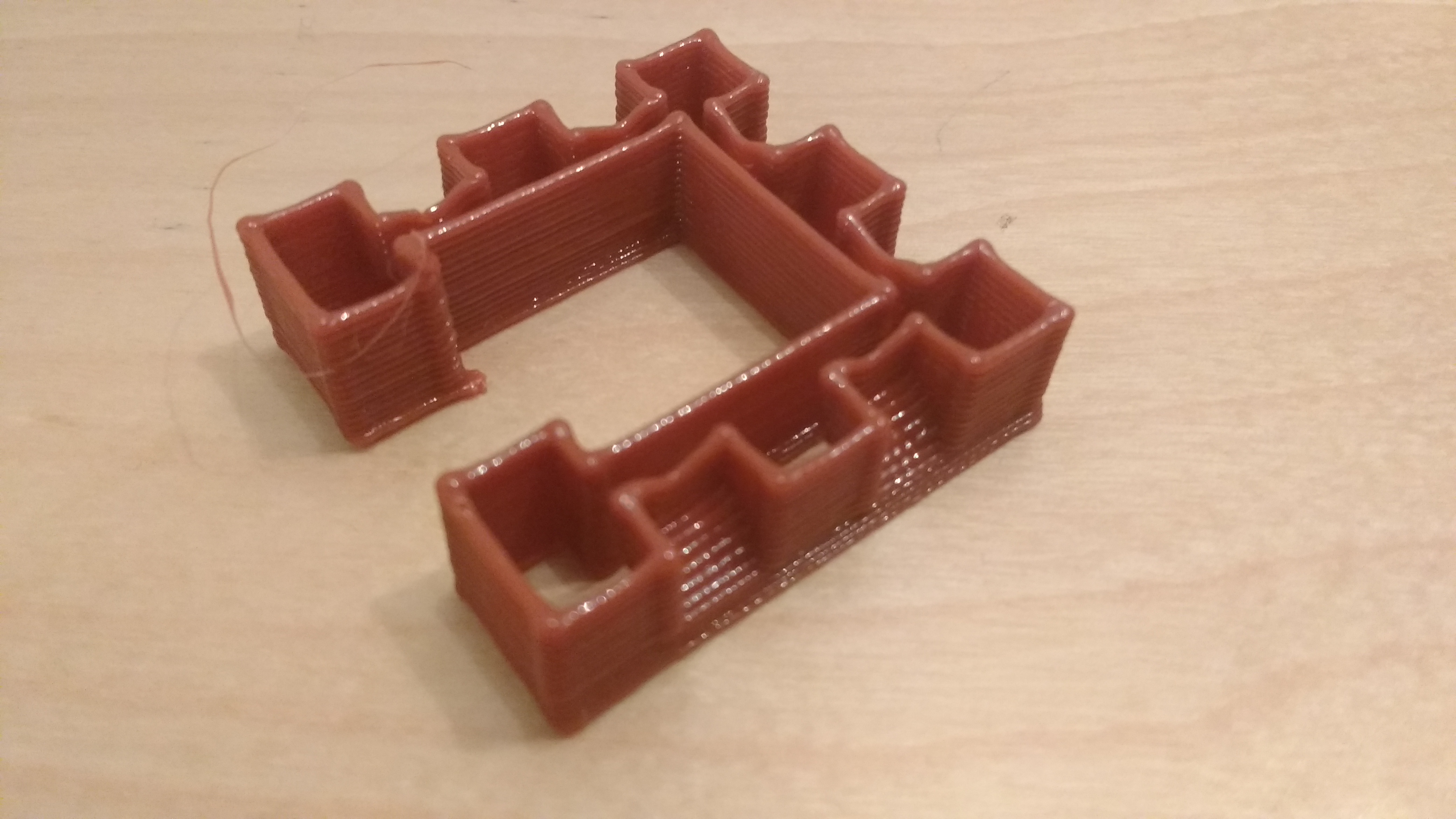
This took two goes as the first time I had the slope at the bottom at too shallow an angle, so they sagged badly. Next I worked my way up the walls:
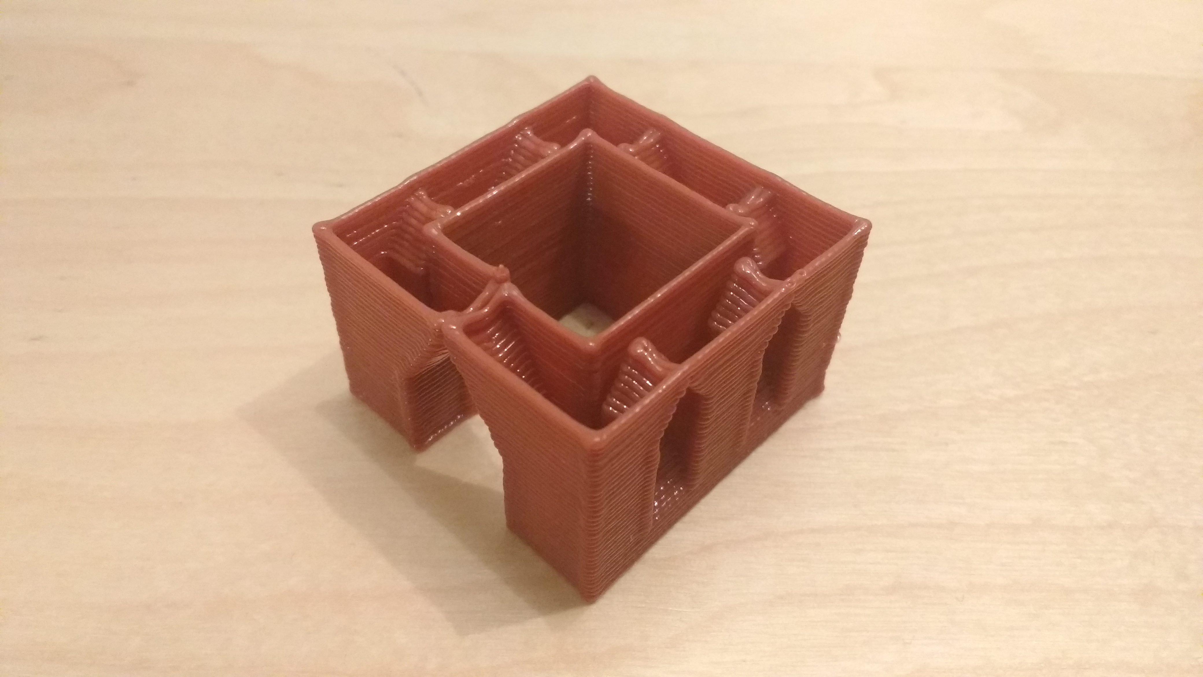
Eventually after some trial I got to the final castle.
Process – First Version
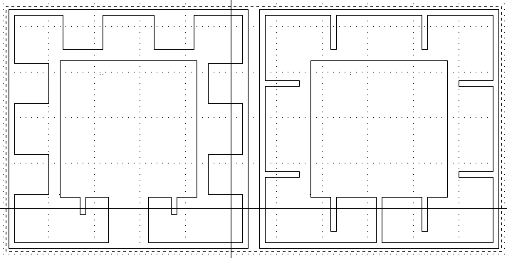
The luck I’d had with the letters couldn’t work with a complex object. I needed to be able to define a layer’s polygon, its position relative to the layer below and some form of order. The simple answer, for me, in Tgif was to have a bounding box, a text object with a number, and a polygon inside the bounding box, as below:
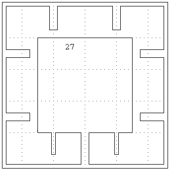
Layer 27, above, is closing up the tops of all the windows and the doorway, along with producing buttresses for the crenelations at the front. So here, there is the box, the number “27” and a polygon – the just visible arrow on the inside bottom left defines the end point of the path for that layer. The line width of the polygon defines how many layers are to be repeated for this path – 1 in this case.
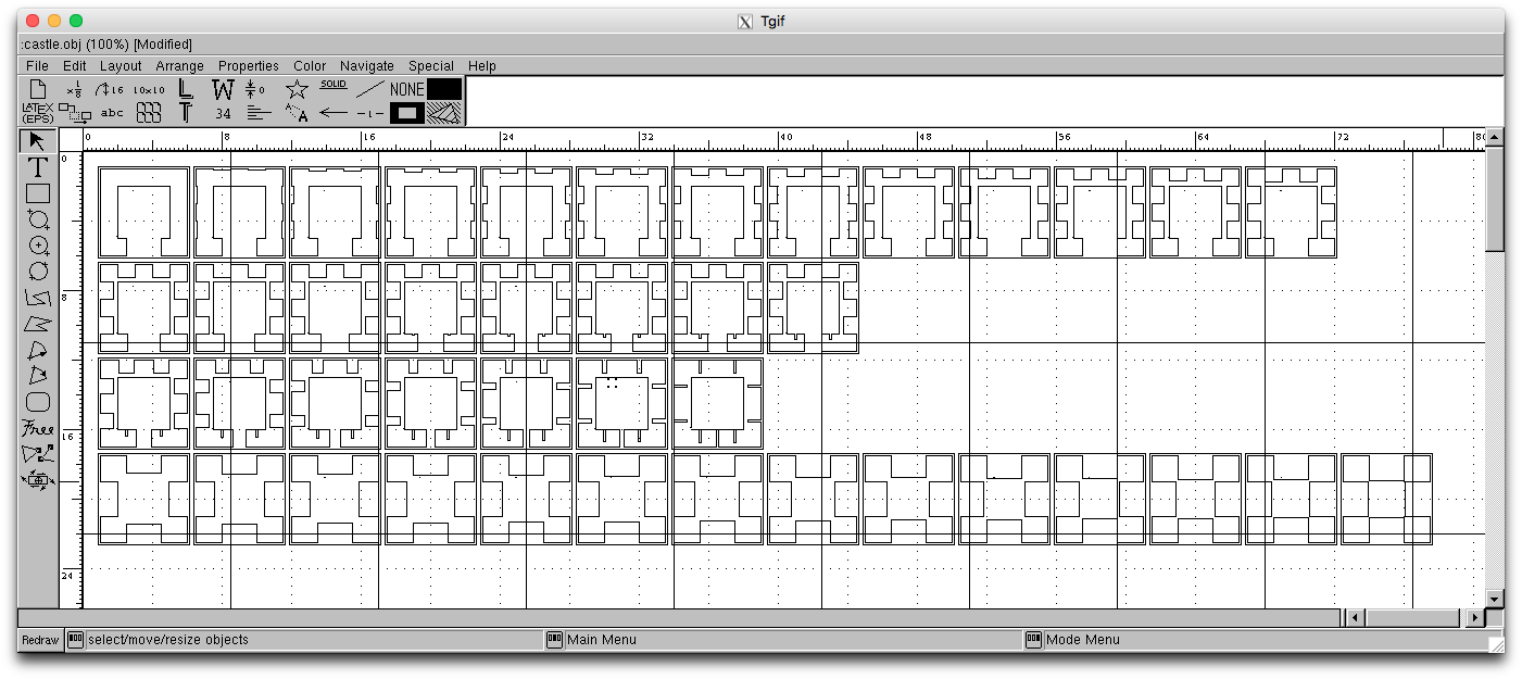
This was a time consuming process, which did work, but resulted in 42 layers. The final Tgif image looked as below:
Process – Second Version
Although the Tgif images, so far worked well, it was a lot of effort. Discussing with a colleague, he asked why I couldn’t define a start and an end and layer-by-layer go from one to the other. A bit of thinking and a new plan came to mind.
The same system of box, text, and polygon would be used by a way of linking a start and an end would be used – a simple dotted box would group two layers together. The layer numbers would define the start and end, and all layers between would be interpolated between the two polygons. Of course both polygons would need the same number of points, but that’s fine.
Some new coding, along with spotting a mistake in my first castle, and I get the new Tgif image of:
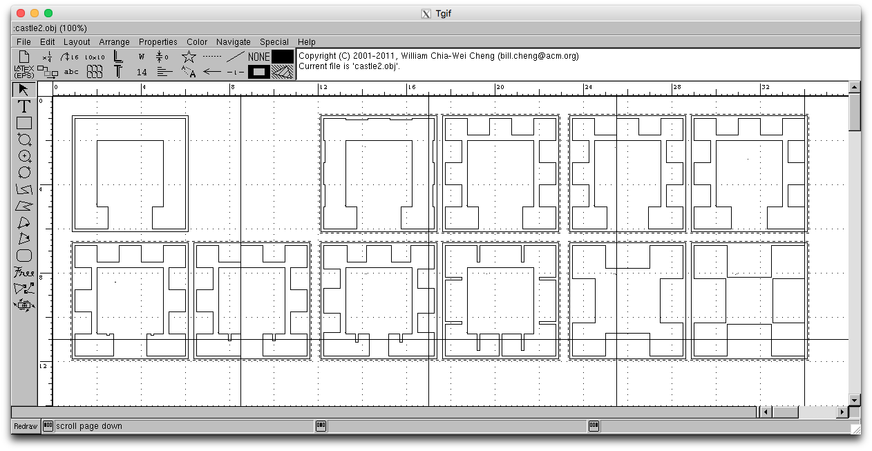
This is so much easier to manage. I’m now thinking on what to make next. I’ll be writing another program that will be able to read in multiple complex models and give a menu to select what to make. Once that’s done, I think I’ll be ready to publish my code – watch this space.