The scarf is now up on eBay. Please be generous in your bids 🙂
The scarf is now up on eBay. Please be generous in your bids 🙂
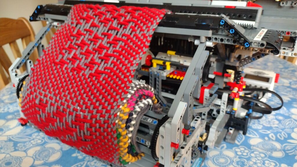
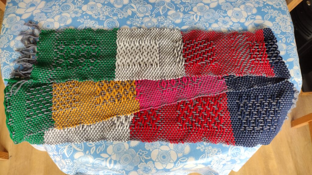
Yesterday I showed several of my robots at the Calder Valley Brick Show, during which my Weav3r loom was making a scarf. This time around I have decided that I shall be auctioning the scarf, via eBay, and the proceeds going to the charity supported by the show: Forget Me Not Children’s Hospice
The loom didn’t quite finish the scarf during the event. As can be seen from the photos, above, there is still a little warp yarn left on the bobbins. I shall complete the scarf over the next couple of days and post an update with photos of the scarf and a link to the eBay auction then.
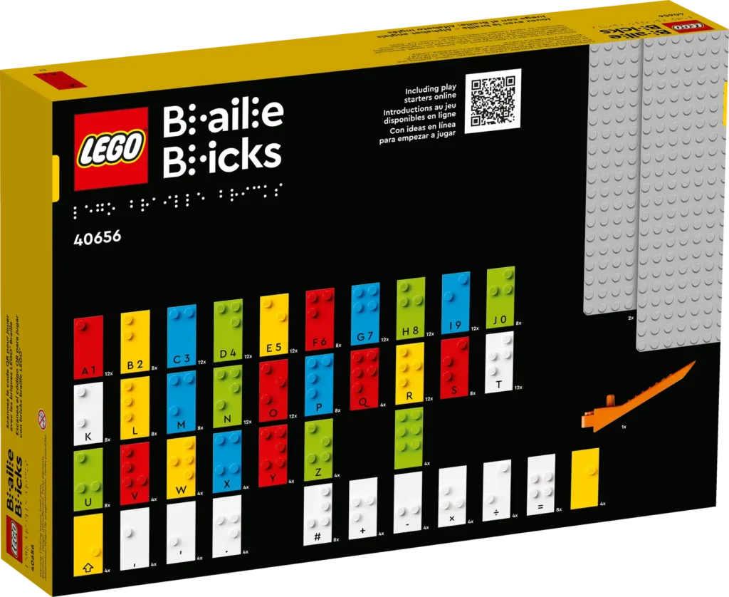
Several months ago I had been thinking on building a robot that could read the Braille bricks developed by LEGO. They have had them available in a more educational context via their https://legobraillebricks.com/ website for some time now. Unfortunately, these ideas came to nought at that time, so I put the idea to bed.
Roll on a few months and the group of RobotMak3rs that I’m a member of had one of their regular remix challenges – i.e. to mix an existing set with some robotics to come up with a new idea. By then the domestic LEGO Braille Bricks set (40656 in the UK) was out, so I figured it was time to revisit my earlier ideas.

Right at the start I wanted the bot to read out the Braille using text-to-speech (TTS). I wanted to do this as the bricks are intended for visually impaired users so having just display of text would be inappropriate. The Spike/Robot Inventor doesn’t have the ability to generate complex sounds on the hub itself and would have relied on an external app running on a mobile or table to perform that task. Instead I decided it would be far better to use an EV3 running Pybricks micropython as that has the ability to perform TTS output. In addition to wanting the Braille read out, I wanted all the prompts that would appear on screen to have an audio equivalent.
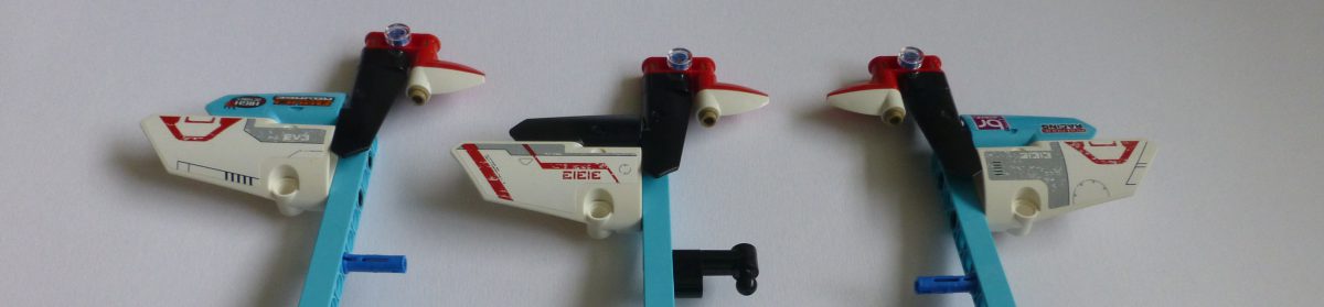
My initial idea for the mechanics was to have three medium EV3 motors each with 3×5 L-beam attached. As the bot moved along the line of Braille it would rotate the motors such that the tip of an L-beam touched either the brick’s stud or the top of the brick. The difference in angle of the motor would indicate a dot or not. However, very quickly this idea was discarded due to the fact that the stud height is only 1.7mm. The height, and therefore angle change was not sufficient to accurately distinguish the presence of a stud or not. Also this would have required three motors, only allowing one remaining to move the bot along a row. Since I wanted to have it be able to read multiple rows of text, I’d have needed 5 motors (X, Y, +3 for touch) which is not possible with an EV3. So I discarded this approach.
My next idea was for a bot that had an arm with three touch switches mounted on it and have the arm lift up and down. This way the angle of the motor would be irrelevant. The arm would need to move up and down on to each column of studs so that it wouldn’t get snagged on the next column as it moved sideways.
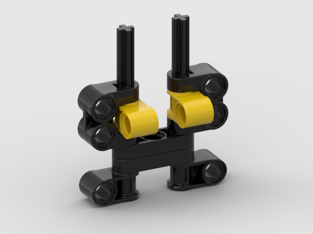
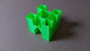
I went through various arrangements of the switches, settling on something similar to below for a number of prototypes:
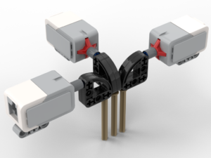
The principle here was that the stud would push against the pin, which in turn via rotation of the 3×3 quarter circle beam would press in the button. The motors would have had to be mounted at 90° to each other due to the width of the switches (initially) preventing them being next to each other. The big problem with all of these designs is that the springs in the switches are remarkably firm. The motor, pushing the arm down, would have to apply a significant force – akin to trying to hold out a 1kg mass at arms length. Also, it looked ugly. I tend to work on the principle that if it’s ugly then it’s likely to be wrong.
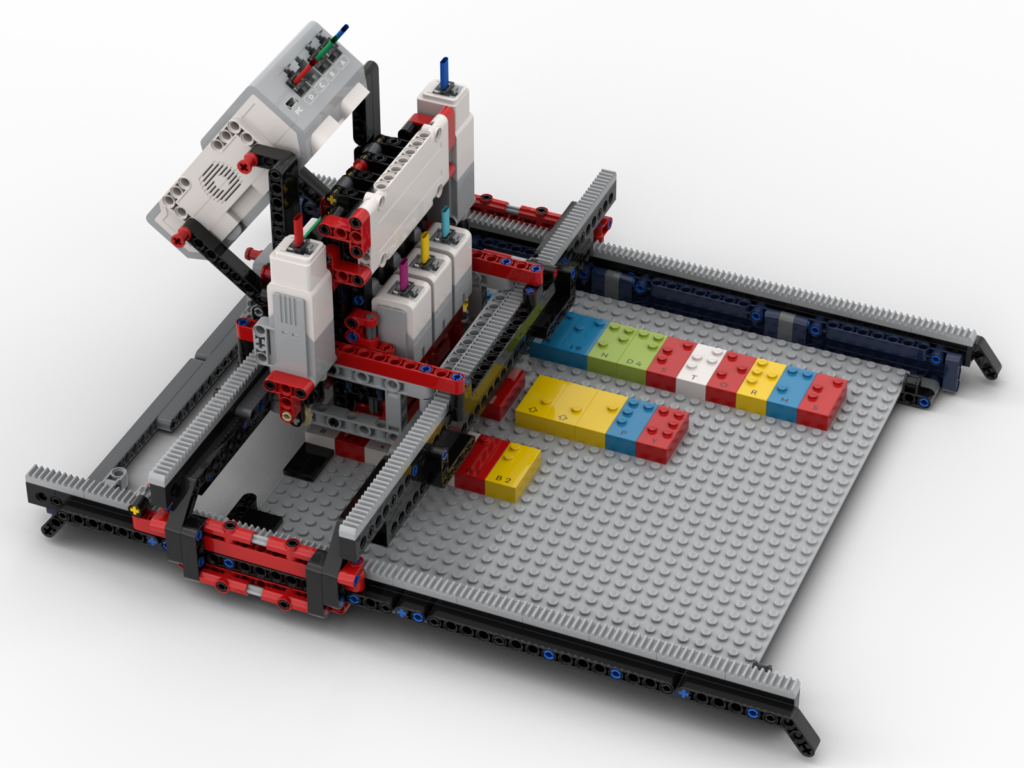
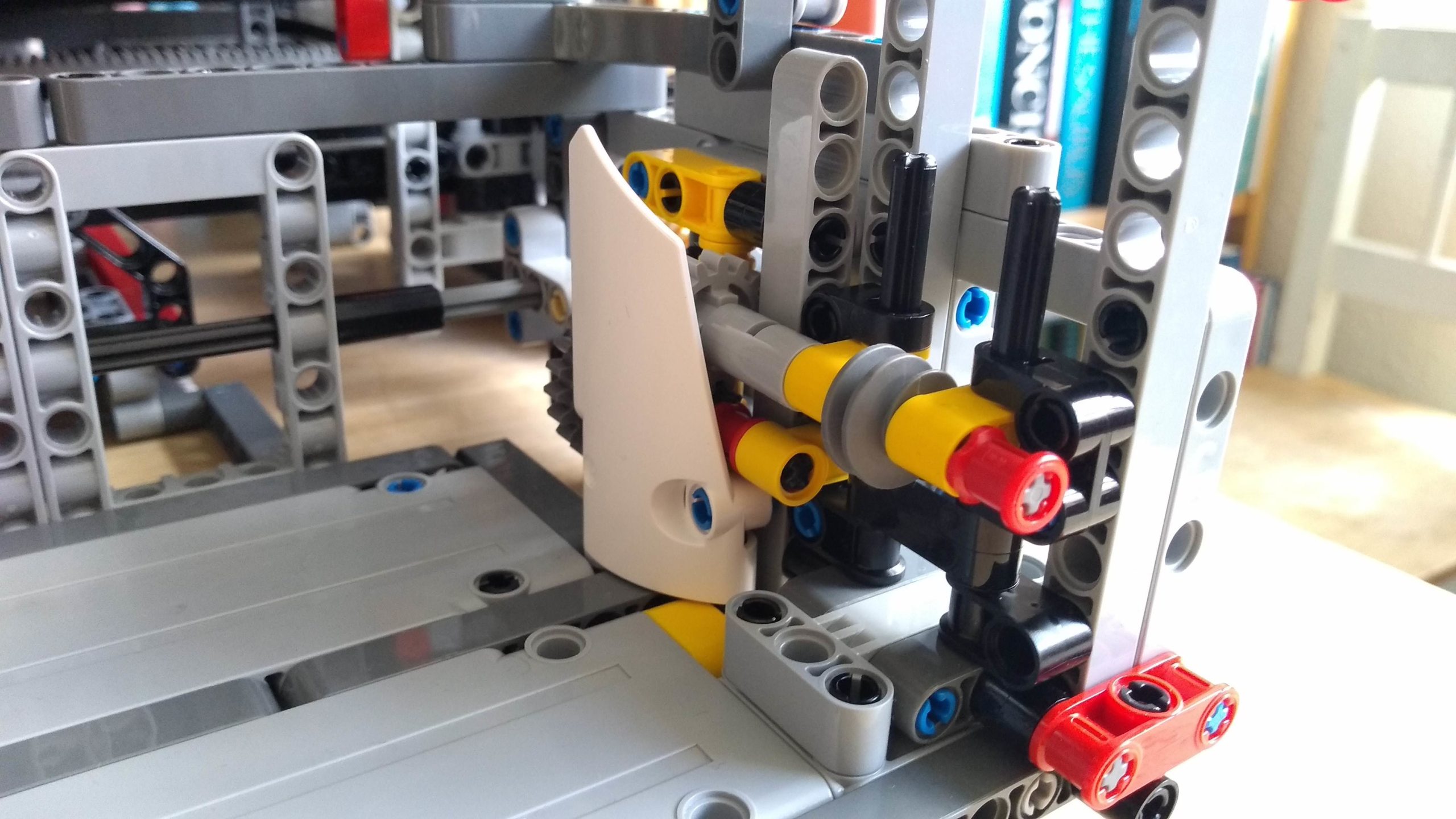
After going through several iterations of the ideas above, I had a brainwave. It was possible to mount the motors in parallel and ‘dog-leg’ the pins such that they could also touch the studs. To counter the issue of the required force to press in the switches, linear actuators would be used instead. Although this would slow down the sensing action it would trade speed against accuracy. I ended up with the mechanism below:
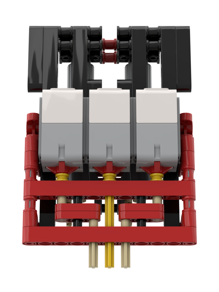
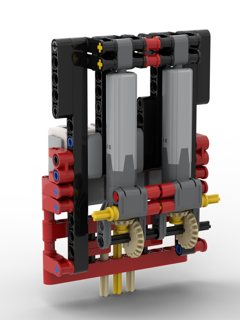
This mechanism worked perfectly, with an unexpected discovery on the switches, discussed further on.
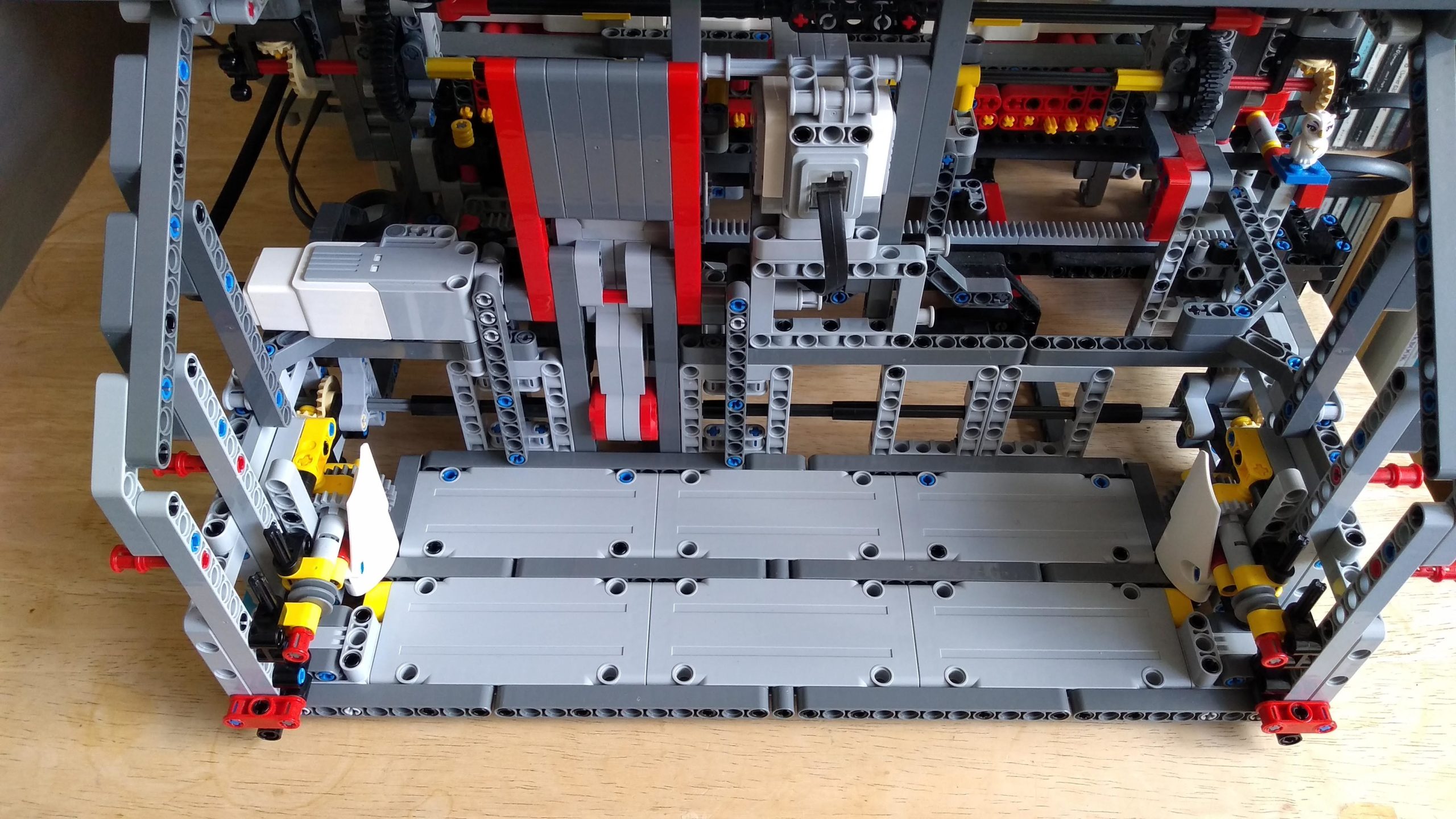
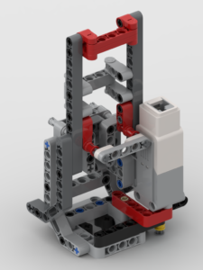
The Braille sensing mechanism (the ‘lift’ as I think of it) needed to move in both X axis and Y axis, so that the several rows of bricks could be placed on the baseboards supplied with the kit. The lift would be mounted on a bridge, allowing for Y-axis movement, and the bridge itself would move in the X-axis. The bridge took a few attempts to get right. Due to a combination of the mass of the lift and the force required to press in the switches resulted in flexing of the bridge, so this required a few revisions to get it rigid enough but not too bulky
One thing I had never realised about the EV3’s switches is that they trigger at the start of their travel, i.e. they don’t need to be pushed all the way in to trigger. Had they needed to be depressed all the way, it’s quite possible this model would never have worked. Due to LEGO being plastic, the parts are never perfectly aligned. This could have meant that one of the switches may have reached the end of its travel before either/both of the other switches had triggered. No amount of extra downward force could have pressed the other two as this switch would have blocked any more movement. Thankfully they trigger at the start, so it’s still possible to push down, thus enabling the neighbouring switches to also trigger.
Due to slight flex in the model, it’s not possible to have the motor wind the linear actuators to the same place per row of Braille. The middle two rows can require a little more force. To solve this the bot requires calibration on first use, and offers to calibrate on start up as well. Calibration requires that an L (⠇) brick is placed at the start of each row, then the bot tests each of those bricks. For each row the motor position for the last switch to activate is stored on disk, for repeat use, then when in use it drives the motor to just beyond the motor angle to ensure that all switches could be activated.
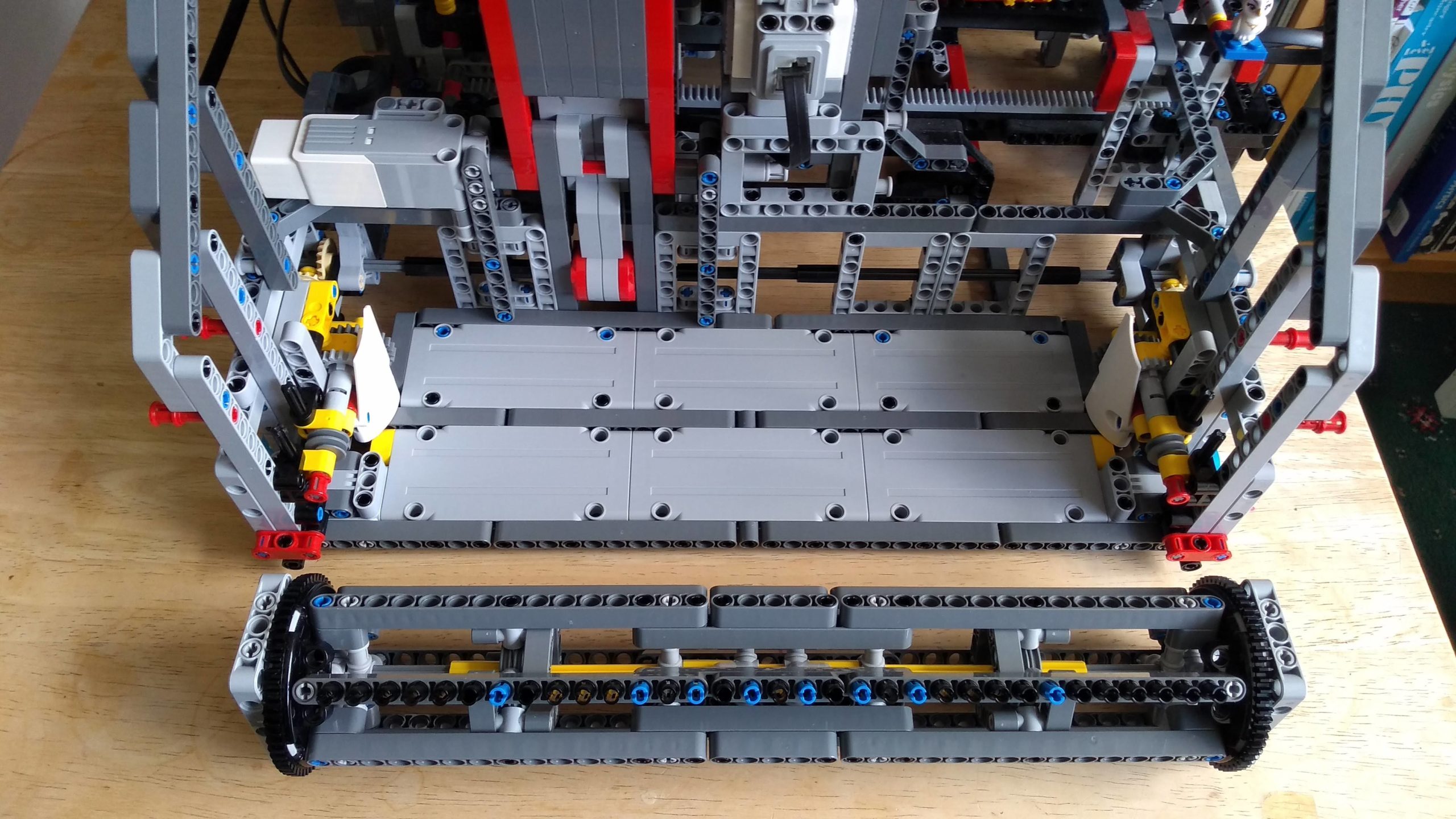
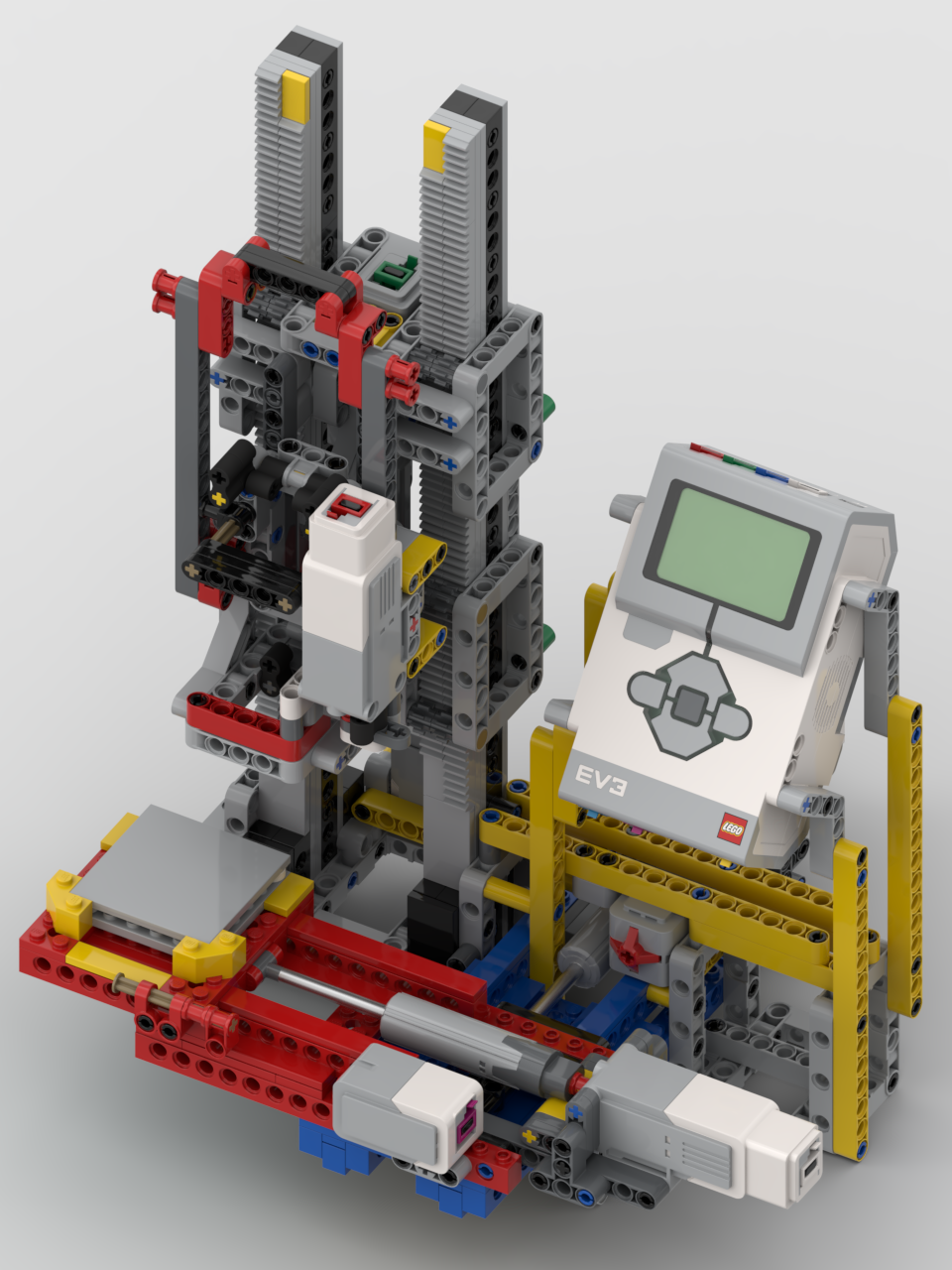
As I said at the start, I wanted this model to be accessible to the target users, so all instructions are read out as well as displayed on screen. All button operations have a small click to provide audio feedback, along with a relevant audio prompt, e.g. saying which row has been selected to read. To aid in placing the Braille bricks on the baseboard there are tiles on the first column. Subsequent bricks are simply placed next to the previous bricks. The EV3 has been oriented so that the speaker is facing the user so that it can be heard.
As part of our group’s remix challenge we have to produce a video relating to our build. I opted to have the video show parts of the robot and it in operation. Since the bot converts the Braille to speech, I figured I’d have the voice-over performed by the bot as well (I’m never a fan of speaking on camera, and being a Brit I always feel that I sound sarcastic 😆). I also thought that it would be a fun little feature to have the subtitles show in Braille first and the wipe over to the actual text. The resulting video is below:
Build instructions: http://jander.me.uk/LEGO/resources/Braill3-BIs.pdf
Python code: http://jander.me.uk/LEGO/resources/braille.zip
The Python code needs to be run under Pybricks micropython, under ev3dev. This requires a microSD card. The official LEGO ev3dev installation can be found at: https://education.lego.com/en-us/product-resources/mindstorms-ev3/teacher-resources/python-for-ev3/
In March 2021 the members of the RobotMak3rs RLOC were challenged to come up with ideas for an Olympic Games remix involving two kits, one robotic and one non-robotic. My idea was to mix the LEGO White House (21054) kit:

and the Robot Inventor (51515) kit (plus four pulley wheels):

to create an Olympic Show Jumping model:
The model has two modes of operation: automaton and game. In automaton mode, the horse will go around the arena leaping over the jumps of its own accord. In game mode, there are speed and jump controls and the player attempts to get the horse’s speed right and jump at the correct time. A video showing the model in operation and some of the details about it is below:
What was not shown in the video is how to start the model off. The model needs to set its initial positions. It does this by rotating the jump motor to its 0° position, then repeatedly rotating the horse motor to its 0° position until the horse ends up in its start position. This is required due to the 36T:60T gearing used to drive the horse’s position. The colour sensor will detect the white 3L beam when it’s in the start position.
The steps to start the model off are:
I have produced build instructions which are linked to below. There are two programs, one for each mode that are also available below. The code has been written in the default block language for the 51515 hub. My BIs and code are released under the Creative Commons Attribution-NonCommercial-ShareAlike 4.0 International licence:
Other models from both the Robotmak3rs and the general community can be found at: https://www.facebook.com/hashtag/robotmak3rsolympics
Over the past week or so, several members (including me) of the RobotMak3rs RLOC have been having a lot of fun playing with LEGO’s new Robot Inventor kit (51515), which will be released on 15th October this year. Many thanks goes to LEGO and the RobotMak3rs RLOC for supporting our ideas.
My idea was for us, as world-wide community, to have fun building some of the models together. Here’s the first of the videos – Charlie:
Watch this space for the other models!
The RobotMak3rs Community Facebook page can be found here: https://www.facebook.com/robotmak3rs/
#mindstorms #robotinventor #robotmak3rs
A little while ago I posted about my new cloth winding drum. Up until that point a lot of it had been built, but I still didn’t have any of the 1L worm gears needed to drive the turntable ends to the drum. Only the 3D LDraw model showed that it’d work.
Since then, I’ve given in and ordered some via BrickOwl. I finally had the opportunity to test the build out and, unfortunately, it didn’t work as intended. The turntables could easily skip off the worm gears under load – loads which it’s likely to see in operation due to the tension in the warp threads. A little bit of investigation showed that the structures that were holding the worm gears in place were flexing under load. There was nothing to stop the split cross-blocks from rotating a little. Since then I’ve redesigned that section to stop that rotation:
This appears to work perfectly 🙂 . Without risking breaking something, I am unable to cause the worm gears to skip on the turntables.
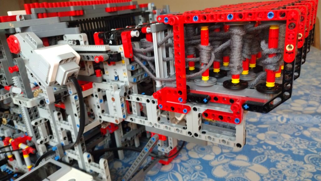
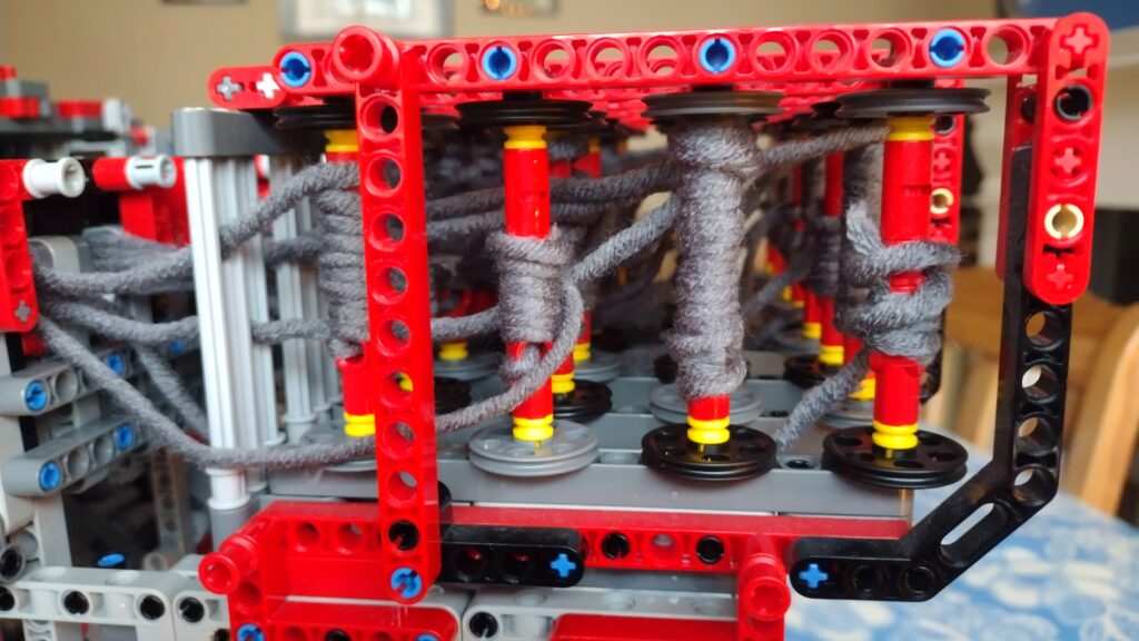
A few photos of the real cloth drum and its update:


The LDraw model has been updated to include the new support:
http://jander.me.uk/LEGO/resources/Cloth%20Winder.ldr
This work is released under the Creative Commons Attribution-NonCommercial-ShareAlike 4.0 International licence.
For some time now I’ve been using the excellent EV3DPrinter, designed by Marc-André Bazergui. The original information on this model can be found at https://www.instructables.com/id/NEW-EV3Dprinter/
To help rebuild his model, Baz had produced a 3D model made in LEGO Digital Designer. That software is almost, if not, obsolete so it’s not so easy now for others to rebuild his model. When I’ve shown it working at exhibitions there has been great interest from people about building their own copy of it – to which I’ve responded that I really ought to make a step-by-step PDF of it for others to follow. I have finally done that.
My build of the EV3DPrinter has been modified. A few sections of it have been altered, and other things have been moved around – e.g. the Y-axis touch sensor is in a different location. In addition to changes to the model I wrote all my own code from scratch, so my sensor and motor ports are different to the original. In addition I have made BIs for an additional pen-holder for a different type of 3D pen.
The BIs for the main model can be obtained from:
http://www.jander.me.uk/LEGO/resources/EV3DPrinter%20JN.pdf
The BIs for the Type 2 pen holder can be obtained from:
http://www.jander.me.uk/LEGO/resources/Pen%20Holder%20Type%202.pdf
The EV3g code can be obtained from:
http://www.jander.me.uk/LEGO/resources/EV3DPrinter_JN.ev3
Additional to the EV3 code you will need some data files for the 3D models, such as the letters or the castle:
These data files are in a zip file that will need to be extracted and all .rtf files downloaded into the EV3 in the same folder as the main code. This file can be obtained from:
http://www.jander.me.uk/LEGO/resources/EV3DPrinter_JN_Data.zip
There are several programs:
When the program starts it will initialise the mechanism. Both the X-axis and Z-axis have adjustable axle stops. The X-axis stop may need to be adjusted to get the base plate central. The Z-axis stop will most definitely need to be adjusted to get the tip of the pen close to the plate. My advice, before starting any printing runs, to manually move the Z-axis elevator to get the pen to the correct height and then alter the sensor axle at the back so that the touch sensor is just pressed. This will ensure that when you start the program that the pen isn’t accidentally driven in to the plate, or that the pen is too high.
After initialising, the program will ask what type of pen is in use: “press and hold” or “on / off”. The original type of pen, as shown on Baz’s instructions, was a “press and hold” version. The 2nd type of pen I have, you press once to start and press again to stop. The program will need to know what style you’re using. The EV3 will remember your last choice and pre-select that at the start of each program.
This work is released under the Creative Commons Attribution-NonCommercial-ShareAlike 4.0 International licence.
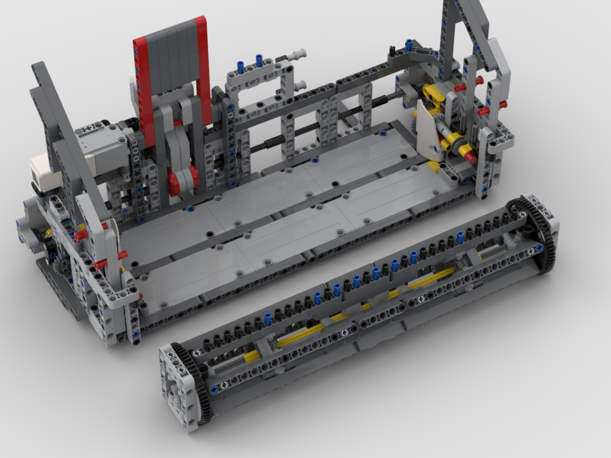
Over the past few weeks I’ve been working on a robotic bobbin winder for my Weav3r loom. Previously, at shows, I’ve had a simple motorised mechanism for winding them but it required my attention to wind. After regular suggestions from Martyn Boogaarts about making a bot to do it, I finally pulled my finger out and got on with designing one:

My intention is to ultimately release the BIs for the loom, but it is taking some time to construct the 3D models for it. One of the issues with the loom is that I’ll need to dismantle significant portions of it to find out how I built it 🙂
I mainly model things for my own benefit so should I have a need to rebuild, I can. For this model, I figured I’d actually produce a proper BI PDF and release that and the code for those that wish to have a go at building it. I should note that I have been a little lazy with the BIs and not run any cables. Instead I have inserted the cable ends and colour-coded them. You will need 1x 50cm, 1x 35cm, and 4x 25cm cables – I’ll leave the routing of them to the builder.
This model will probably need an instruction manual, although I’m hopeful that it ought to be relatively clear how it works. The video above shows how the yarn is threaded through but that ought to be obvious. The code has a menu system which also ought to be clear. If there’s enough feedback/demand for operation instructions, I’ll write up a blog article/document to do that.
The code and model are released under the Creative Commons Attribution-NonCommercial-ShareAlike 4.0 International licence.
The code can be obtained from: http://jander.me.uk/LEGO/resources/Bobbin%20Wind3r.ev3
The BI PDF can be obtained from: http://jander.me.uk/LEGO/resources/Bobbin%20Wind3r.pdf
Whilst we’re all in the position that we need to reduce social contact due to COVID-19, I have taken the opportunity to work on a couple of aspects about my Weav3r loom that I felt needed attention. I have definitely solved one of them and hope, when I can buy some parts, that I have solved the other.
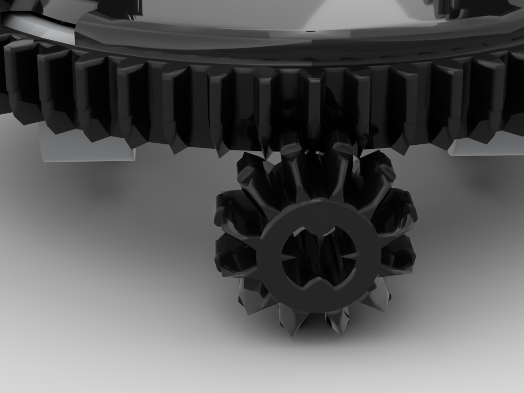
This is the problem I hope to have solved, but don’t yet have conclusive proof. Whilst working on the problem of the concentric drive I found that the mesh between the usual 12T gear and the 60T turntable was not particularly good. Looking at the image below it can be seen that the teeth of the 12T gear approach at quite a shallow angle to the 60T. This can be seen at the 11 and 1 o’clock positions – the teeth of the turntable appear to “dig in” to the 12T gear. This causes the mesh between these gears to sometimes be very rough.
When working on the concentric drive I found that the 20T gear is a much better mesh, but this requires a 1/2L offset which really just didn’t work for the loom. The other issue with using a bevel gear to drive the turntable is that the tension in the warp thread could feasibly be high enough that as the turntable rotated it would be pulled up and away from its drive gear which could also produce the same clicking problem.
The change to the gear chain has been to have the worm gear driving the turntable. This is a great benefit as the worm drive is a much smoother mesh and, also, it is not possible for the turntable to lift off the worm. To drive the 60T turntable with a worm gear I will need to use the newer 1L type – this is the part I don’t have, but have rebuilt with the intent to use.
The existing gear chain was: 1 • 20:12 • 1:24 • 12:60 => 1:72. This used one of the old 3L worm gears, halfway down the gear chain. To use the 1L worm at the end, with the same axle paths from the large motor, the gear chain is now: 1 • 20:12 • 24:24 • 8:16 • 1:60 => 1:72, so the same ratio. However, the additional 24:24 will have reversed the direction, so I must remember to adjust my code to reflect that.
The new turntable drive now looks like the image below:
The original build’s drum was locked in to the structure. This meant that to remove the scarf, at the end of a day’s show, the whole thing had to be run in reverse for around 3m. This would take a remarkably long time, and was just extra wear and tear on the mechanism that could be avoided. So, another design criterion for this change was to make the drum removable, but at the same time retain its strong connection to the worm gear. This has, happily, been achieved.
The drum has a 5 x 7 open centred frame at each end which locks in just above the worm gear. In the image above it’s possible to see two 4L axles with stop either side and behind the worm gear. These lock in to the bottom of the drum’s end frame preventing any misalignment. The frame is locked in to place by two bush pins inserted from behind.
The drum itself has also been altered. The original was somewhat flexible and the pins along one “side” had a gap in them. The inner “hexagons” inside now have two pulley wheels inside to support them, making the drum more rigid. The structure has also been reworked to remove the gap in the pins. An added benefit to that is that there are 33 continuous pins, which equates to 32 slots between them, one per warp thread. An intermediate render, I’ve changed things a little since I made it such as the black bush pins are in the wrong place now, is shown below:
The entire front structure that encloses the drum is removable for transportation, i.e. for DHL to take it abroad 🙂 This has had some attention at the back of it, but that is more cosmetic and tidies a few things up. One humorous thing is that when I’ve detached it recently I’ve partially dismantled a section – I’d totally forgotten I’d built it so that I pull out 4 bush pins and the whole unit lowers down and forward!
Renders of the final structure with the drum installed, and removed, are shown below.


An animated render of the structure is below:
For those that may be interested, I’m posting the LDraw model. I don’t intend producing a PDF of BIs, but this model is in steps, so should be easy to follow. This work is released under the Creative Commons Attribution-NonCommercial-ShareAlike 4.0 International licence.
Over the past few days I’ve been rather nerd-sniped in to thinking about a system for passing two concentric drives through a turntable.
I’m starting to think on ideas for a bot that I plan to build later this year. This bot will need an “arm” attached to a turntable, with two motorised functions attached to it. There will be driven functions on either side of the turntable and it must be able to rotate an indefinite number of degrees, so passing cables through the turntable is not an option. This leads to the only conclusion that the two driven functions on the arm must be driven by axles passing through the middle of the turntable.
Two parallel axles don’t work, as when the turntable rotates, how does one keep the gears attached? The answer is to use concentric drive shafts. This can be done either using driving rings, or a 16T/24T empty differential. The former is no good for my bot due to the ~90° backlash in a driving ring, and thankfully I had one of the latter!
The next issue is what I’m mainly blogging about – when the turntable rotates, the concentric shafts need to rotate in unison. I could achieve that, to pretty good success, by driving all three motors at the same time at appropriate ratios – but where’s the fun in that? Instead I’ve opted for using two additional differentials as adder/subtractors on the input shafts for the concentric drive. So, as the turntable rotates the two differentials add/subtract a proportional amount from the other two inputs, so it all rotates together. It’s hard to describe, but it does work.
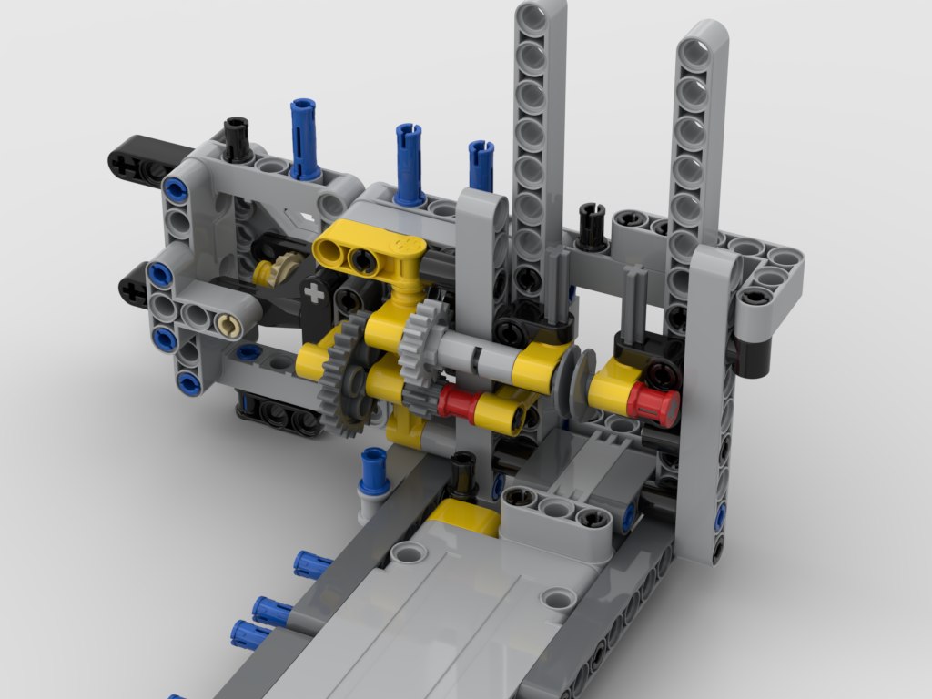
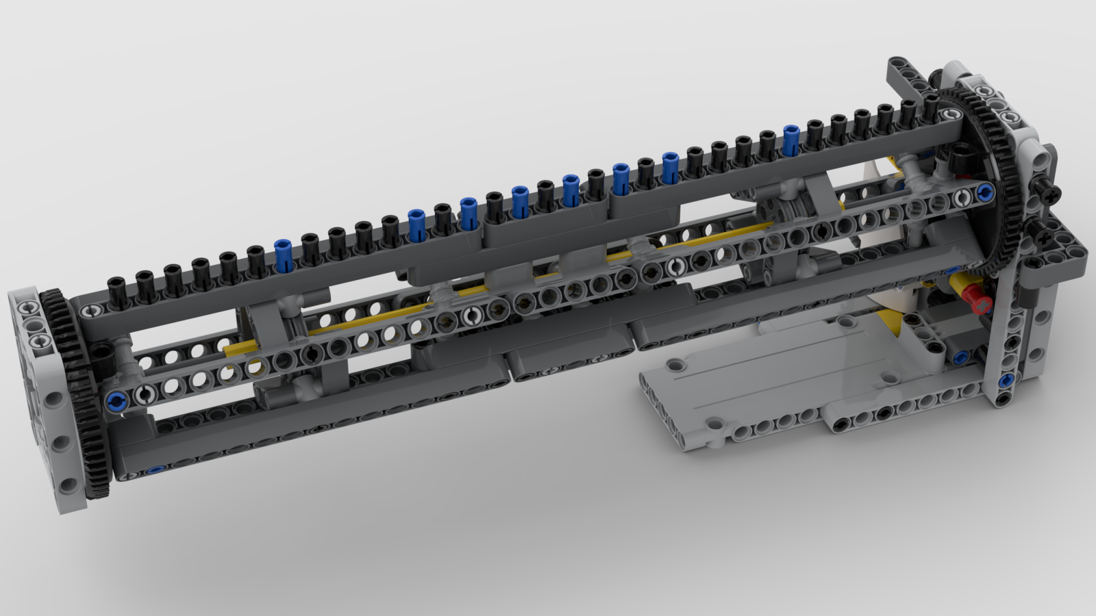
For this all to work, for each rotation of the turntable I need to have a half turn of the differentials – that results in a full rotation of the output side of the diffs. That turned out the be easier said than done. The turntable has 60 teeth, and the diffs have 28 teeth. So I needed a 60:14 ratio. Thankfully I have a SPIKE Prime, which has two of the new 28 teeth gears 😀 This works out to be: 60 *28/36 * 12/20 * 16/24 * 12/16 = 14. My resultant mechanism looks like below:
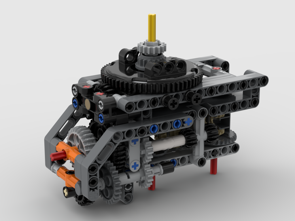
The two input shaft, red axles, at the bottom drive the two 16T gear outputs above the turntable. The red input axle on the left drives the turntable. This is as compact as I could make it.
One thing to note is the 1/2 offset 20T bevel gear that drives the turntable, as an idler gear. Normally a 12T bevel gear at normal spacing would be used. Originally I did have that but it was incredibly noisy and “crunchy”. After lots of inspection under various lights, even trying a bit of silicone lubricant I realised the issue – the 12T gear was binding up against the teeth of the 60T turntable due the the teeths’ angle of contact. As a “new” tooth from the 12T gear approaches one of the teeth on the 60T gear, the angle is too steep, resulting in the 12T gear pushing the 60T gear up rather than across. This would explain issues I’ve had with my loom clicking loudly at times – the front cloth winding roller is also a 12T/60T combination. The same must be happening there. The answer here was to use a 20T gear, but that required a 1/2 offset which was an interesting challenge to fit it, but it now works a treat.
I’m a few months away from actually implementing my ideas – I have lots of things for the loom to do first – but at least I have got my nerd sniped brain over this problem. I’ve made an LDraw model of it, but haven’t got the time to turn it into full build instructions. This is being released under the Creative Commons Attribution-ShareAlike 4.0 International License and is available from: