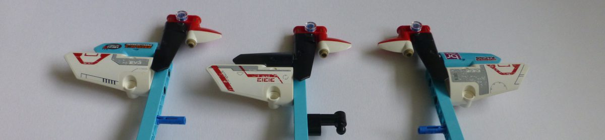
So, I’m currently in the process of developing my latest project: WEAV3R. This is to be a fully programmable “Jacquard” loom, i.e. apart from doing plain weave, it can do twills and, even more importantly, damask patterned weaves. Here’s a teaser of the heddles going through a twill pattern:
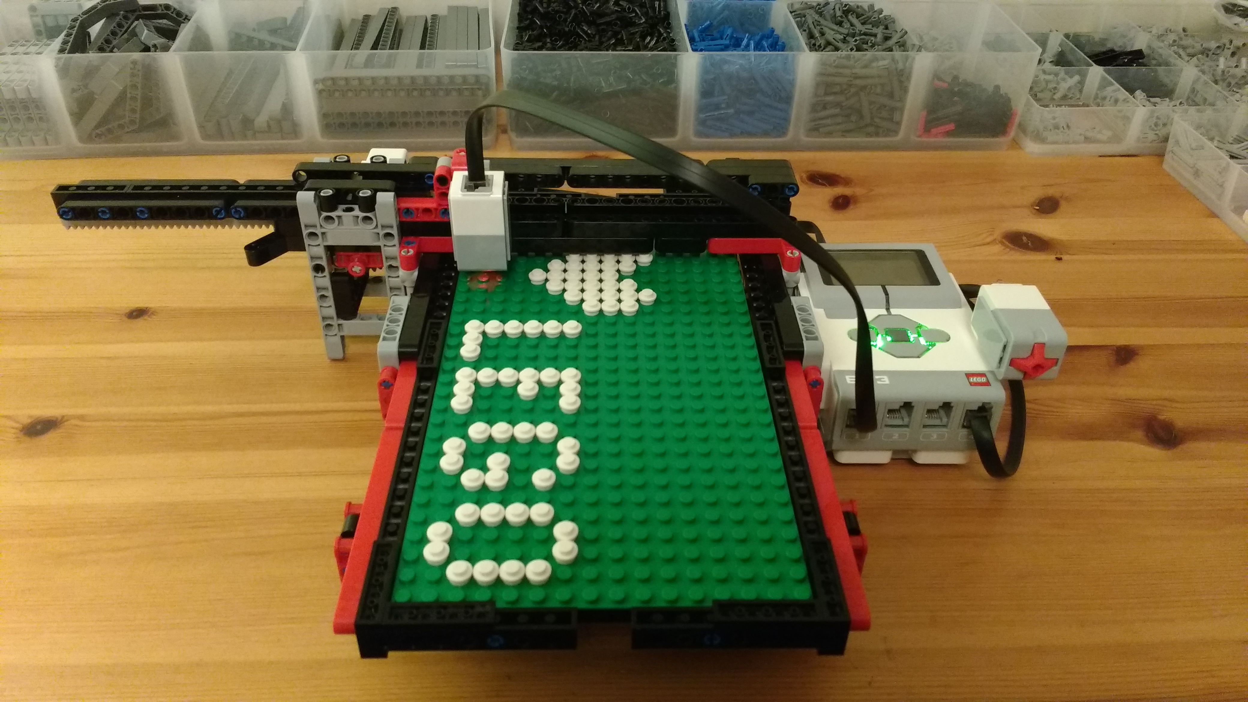
But, that’s not what this post is about 🙂 What I’m commenting on is the joy of redesigning a model, or part thereof, to make it right. Where I’m up to with the WEAV3R is the pattern input scanner. This is so that people can create a pattern on a 16 x 32 baseboard and for it to be woven into the cloth (well, most probably scarf as it’s only 32 warps wide). An example of a baseboard pattern is below:

This board is then placed in a holder, and then that in to a scanner:

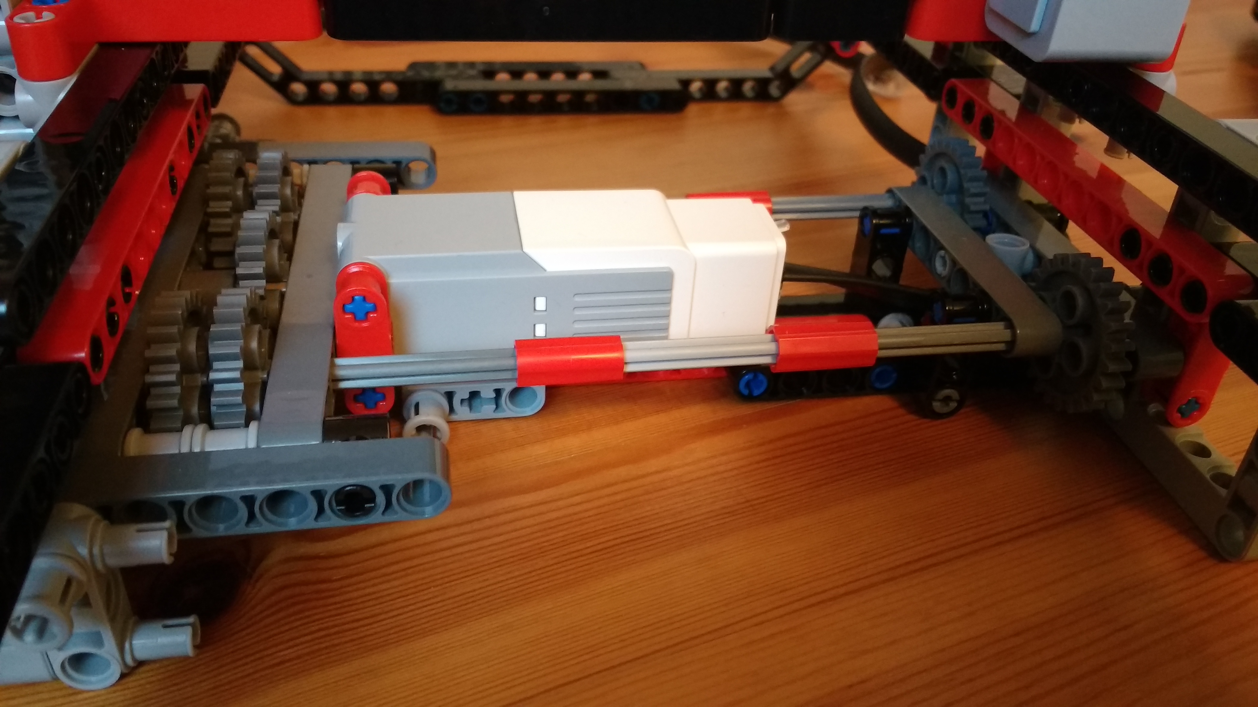
Now, I was happy with my design on the whole, but I started to see a snag/annoyance. The scanner underneath, looked like the image below, along with a zoom in on the drive gearing:
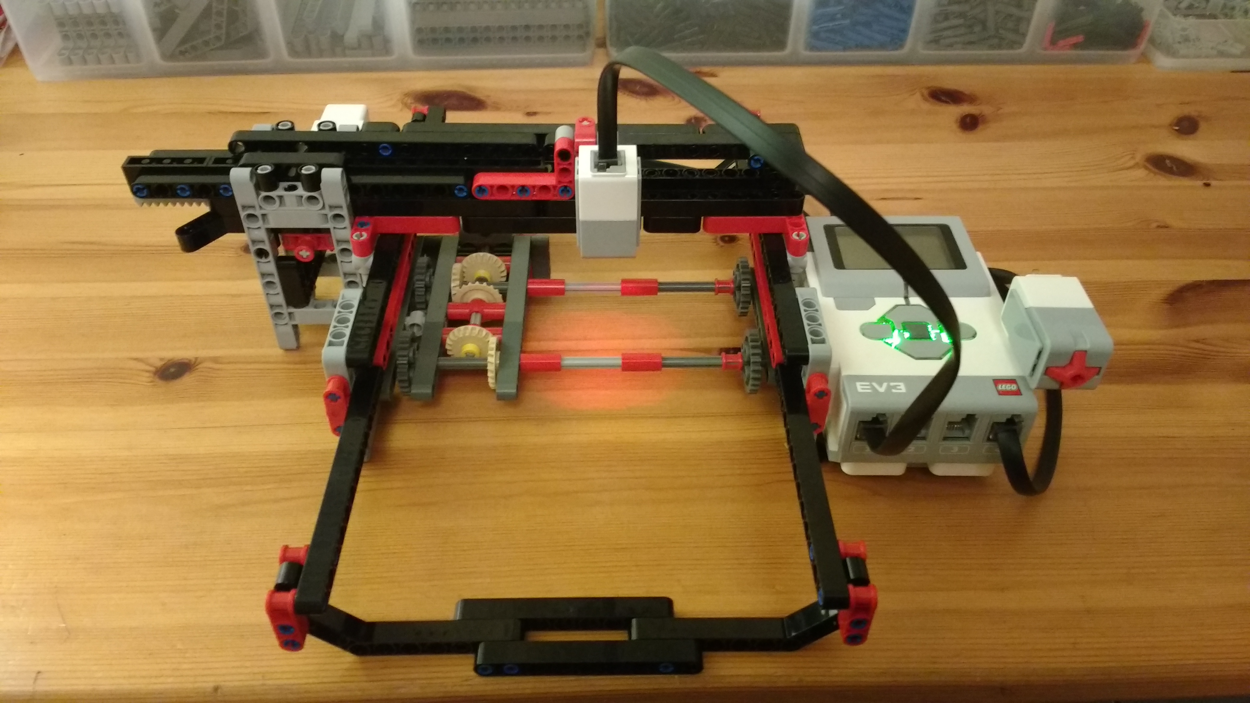
The frame that holds the baseboard for scanning has two rows of 1 x 4 racks underneath, which are driven by the pairs of 24T grey gears either side of the scanner. I use two pairs as I have a need to scan beyond the ends of the board for calibration purposes, and they both need to be driven hence the “gear box”. It’s this gearbox that started to annoy. There is a medium motor at the back driving the first of the 20T beige gears. Due to the other 20T gears in between the second 24T gear has a reasonable amount of backlash. Thus when the racks roll from one joined pair of gears to the other there is a slight mismatch in the orientation of the teeth, causing a clunk noise, and a small judder.
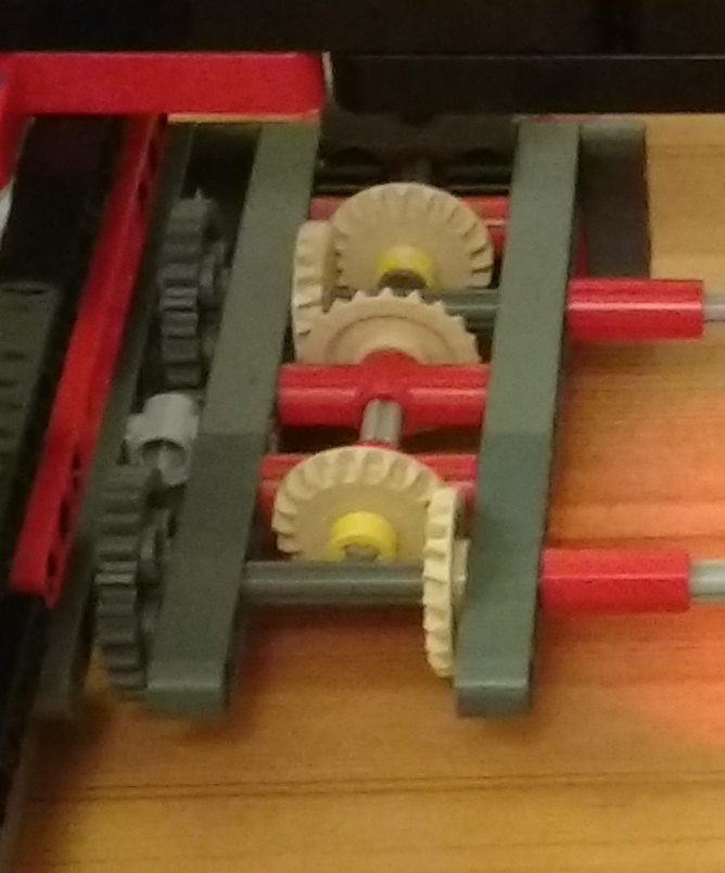
Okay, time for a redesign. Rather than use a gear box I’ll mount the medium motor between the paired gears, and drive them centrally. This has the benefit that both rack drive gears will always be in the same driven orientation. The new motor and gear arrangement is as below:
Brilliant! It’s all nice and neat, rigid enough and no mismatched backlash. That’ll work perfectly … oh no it won’t! 🙁 The scanning frame is now catching on the top of the motor – D’oh. The frame looked like below:
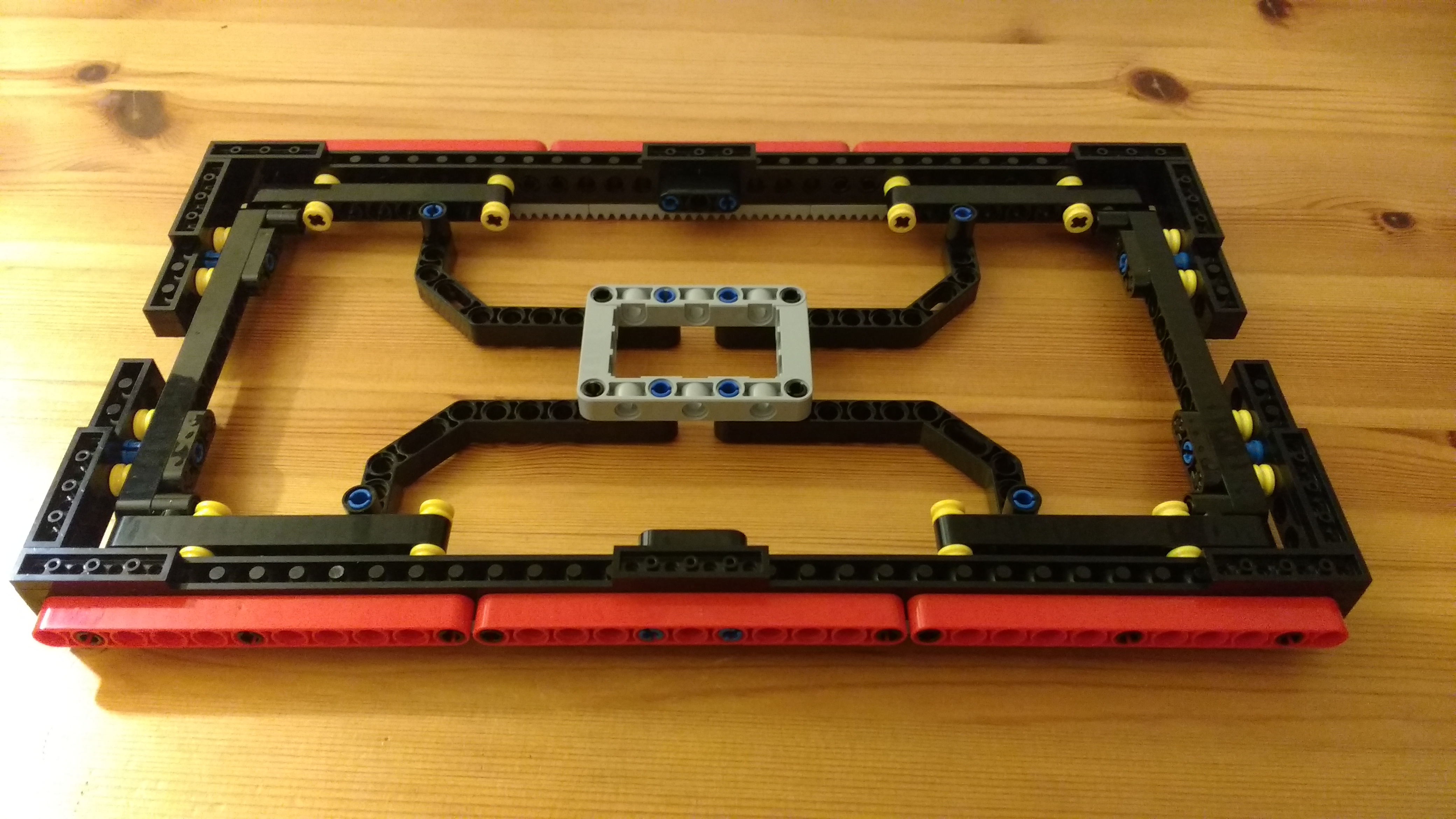
This shows the top view. The central frame and 45° bent lift arms are to make it more rigid. The issue I now had hit is that the frame, when sitting in its slot, is riding very slightly low due to the 7mm / 8mm beam dimensions along with a very slight droop in the lift arms due to the weight. The lift arms needed to be removed or raised up by one beam’s height. Due to the location of holes this just couldn’t happen in the space allowed. Some pondering and some tinkering this morning I came up with:
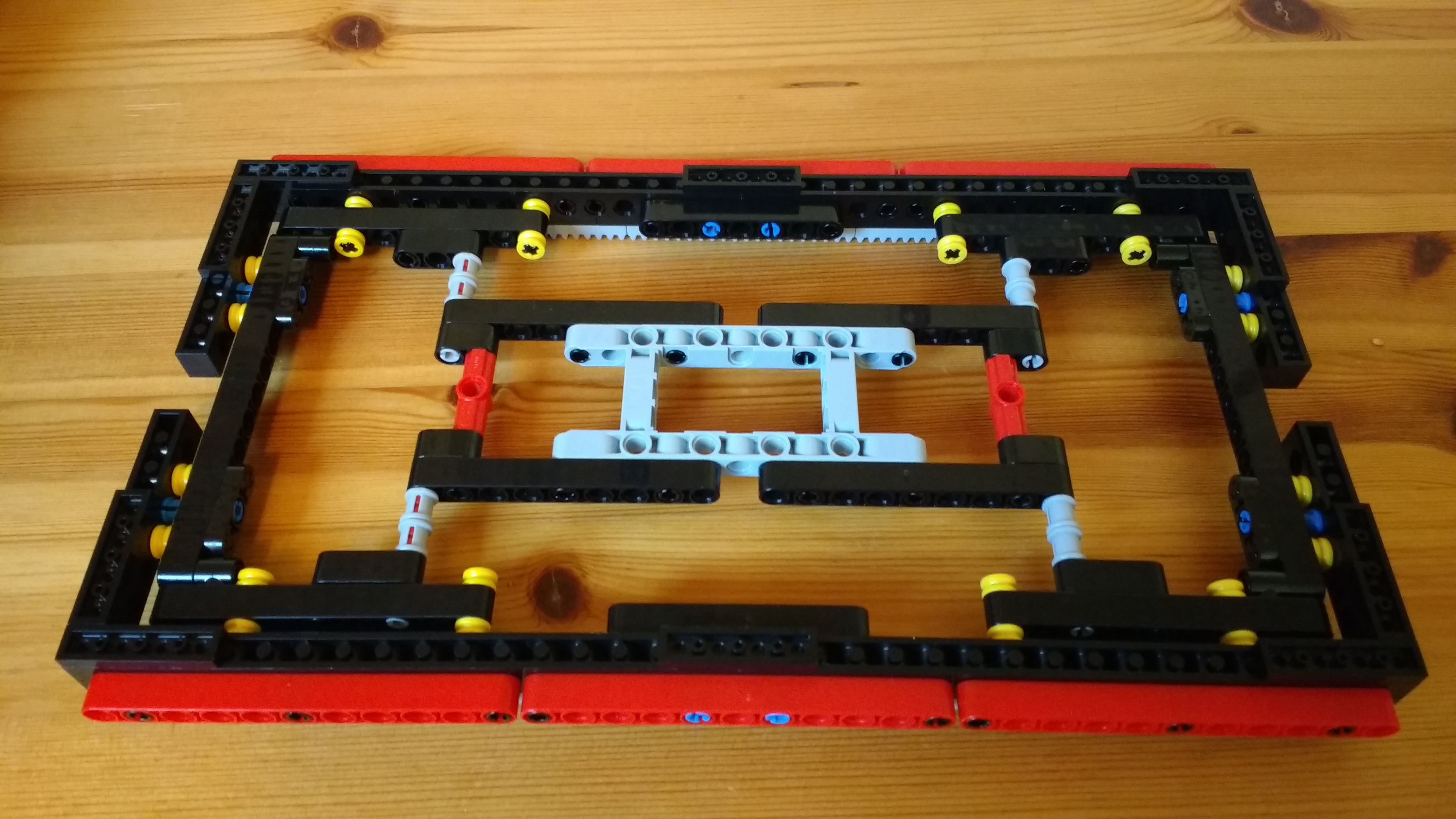
So overall the same level of rigidity without too much extra mass to worry about [It’s been slightly altered since then, but only cosmetic].
So, as usual, redesigning one section has a knock-on to other areas 🙂 This is all part of the fun of building things to me. The Jacquard selector mechanism for the loom is on revision 8 at least, as I’ve built that up and had to go back on sections. The worst of course is where one has to dismantle almost the whole thing to change a small inner part 😉 I think that happened on revisions 5-7 of the Jacquard!
Over the next couple of weeks, as I get time, I’ll get on and code the scanner up and post a video of it at work. That in itself will be an interesting challenge, especially as I want it to send the resultant scan, via Bluetooth Mailbox messages to the 2nd EV3 that’ll be driving the Jacquard.
Watch this space …