I’ve been working on the loom for some time now, trying to iron out some of the issues with it. The main issues were down to the pattern setter, the ‘Jacquard’, getting jammed. This was mainly down to two problems: 1) uncontrolled tension in the warp threads, and 2) vibrations during weaving causing the floating pins to move out of place. To explain these issues, I built a demonstration model.
Demonstration
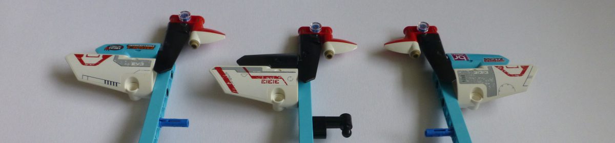
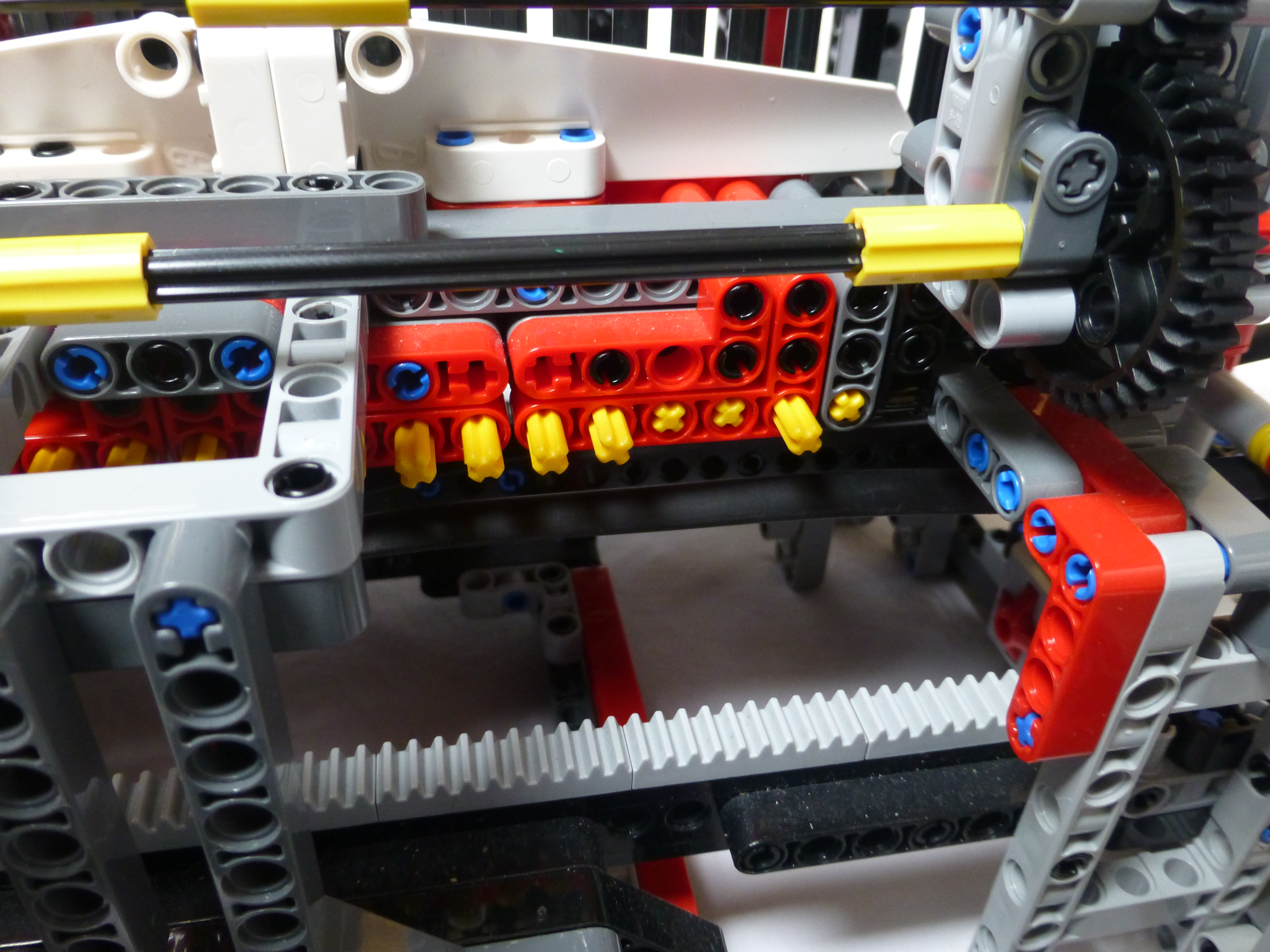
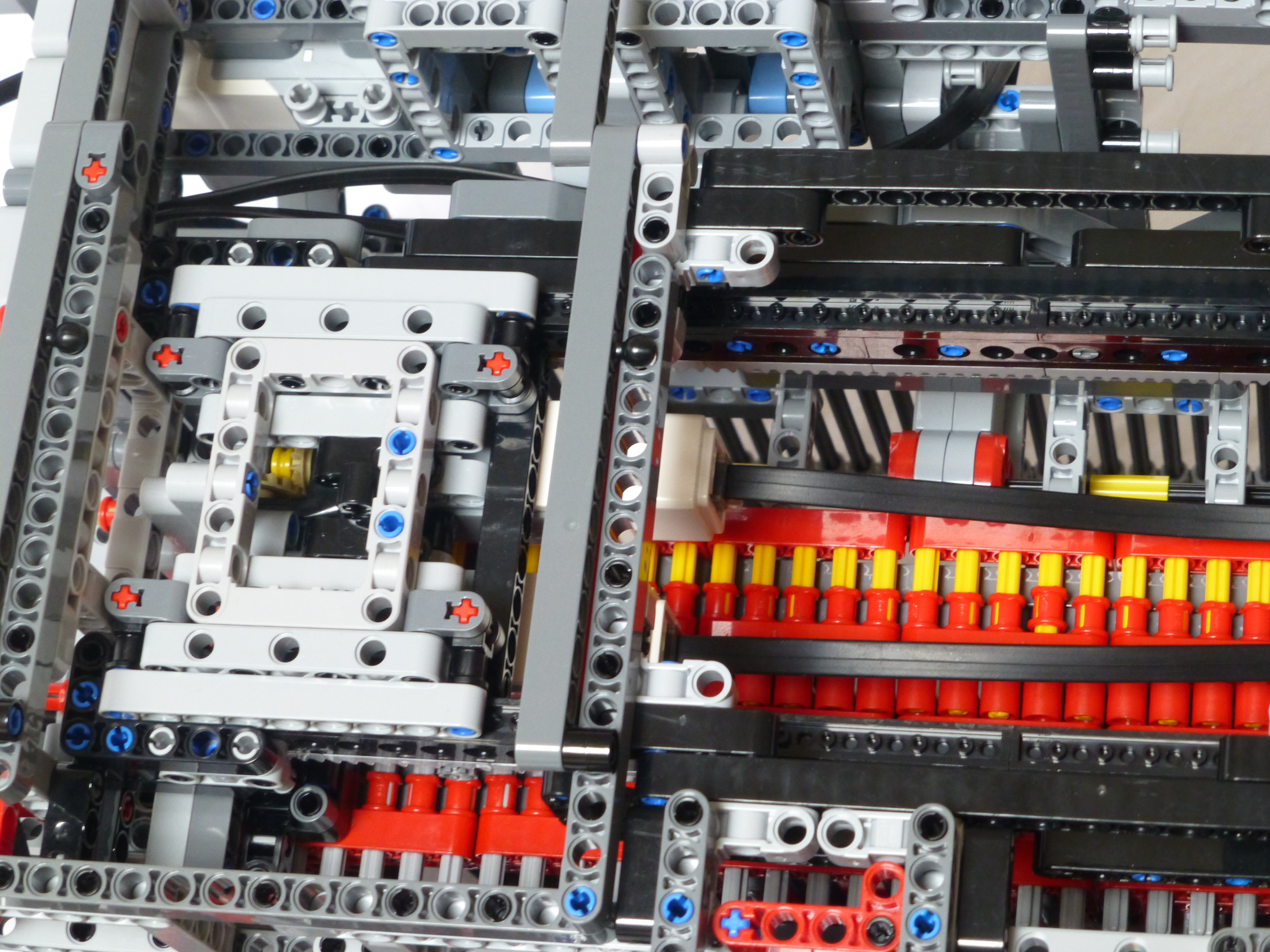
When I’ve shown the loom off at exhibitions, I’ve struggled to explain, easily, how the pattern setting mechanism works. So, to make it simpler I built a little model of the mechanism, as shown in the picture below. There are two beams with floating pins inside. The picture below shows the front beam with 3/5 of the pins set forward. The beam behind the vertical yellow axles, the “heddles”, can lift upward.
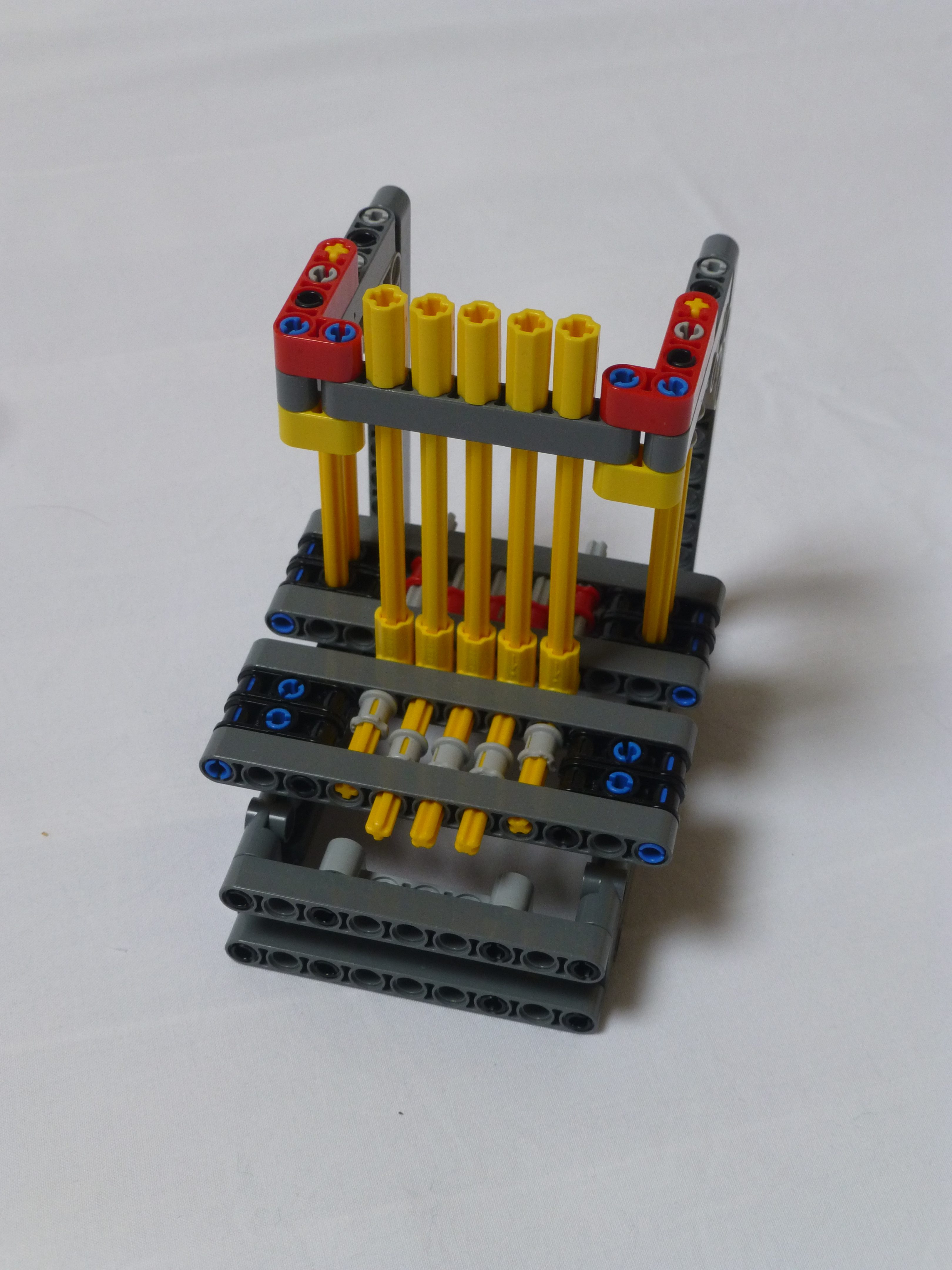
The picture below shows the lifting beam in the upmost location, thus showing how the patterns are set on the heddles.
Both of the pictures above also show where the problems with the loom occur.
Problem #1
The first problem is when setting the pattern. The loom needs the heddles to be in their lowest position for the pins to move back and forth. In the original build of the loom, there was only one way of maintaining tension in the warp threads which was by applying friction to the warp thread supply drum. Due to how the loom was loaded with threads, and this drum wound, it was probable that the tensions would be mismatched across the threads. As the loom worked though row by row, some threads could end up much higher tension than the others. This would cause issues when the setter beam needed to drop as it couldn’t pull down against that tension, resulting in the setter beam being slightly crooked. When the pin setter tried to move the pins, they would not line up with the rear bar’s holes resulting in the entire mechanism jamming up.
Problem #2
The second picture shows how the vibrations could be a problem. As the shuttle would pass from side to side there would be a small amount of vibration, or buzz, from the motors. This would cause the unsecured pins on the front beam to precess backwards, under the heddles that had been lifted. Again, when the bar was lowered it would not be able to move to its lowest position due to these precessed pins blocking its path.
Solution #1
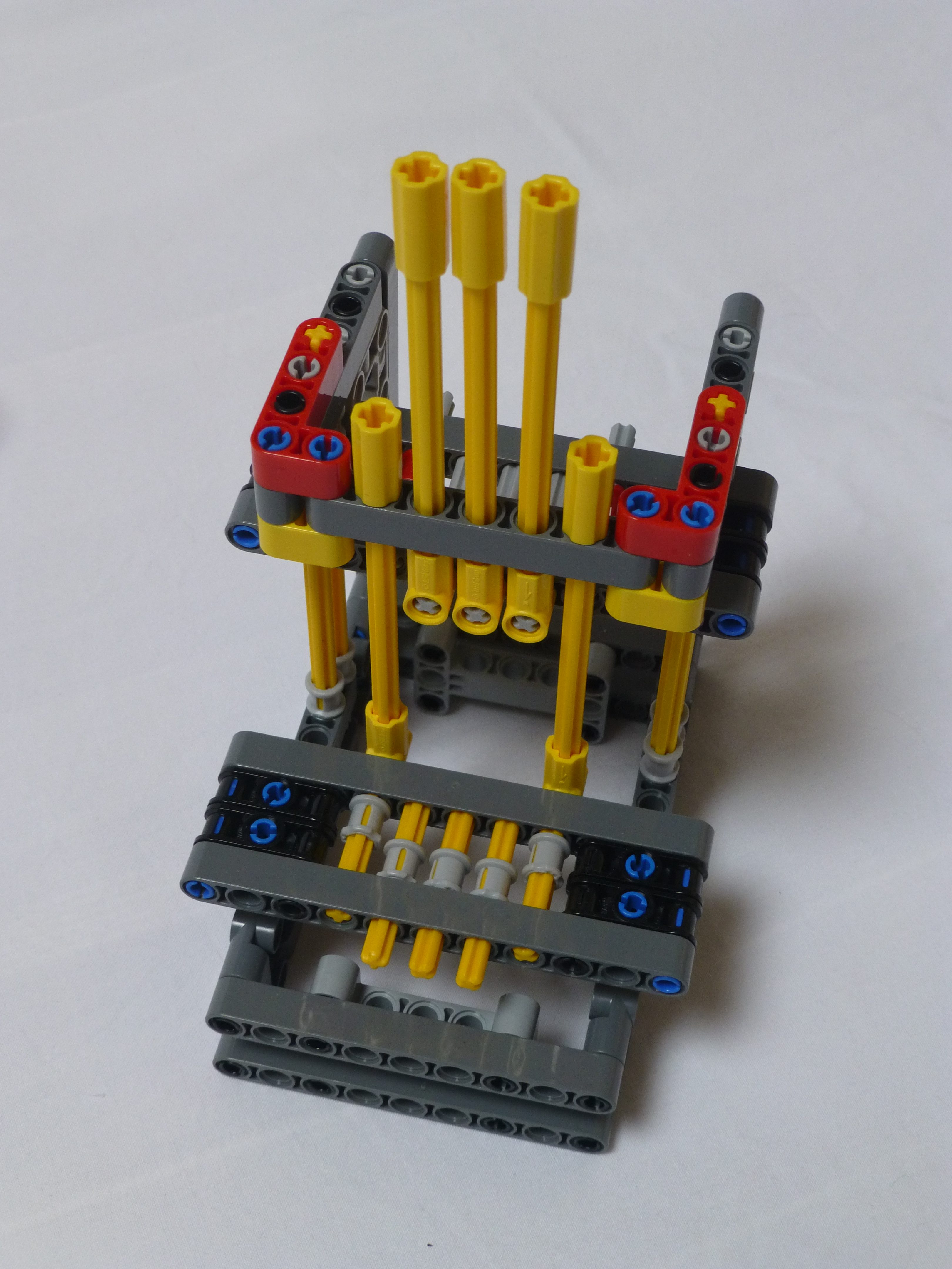
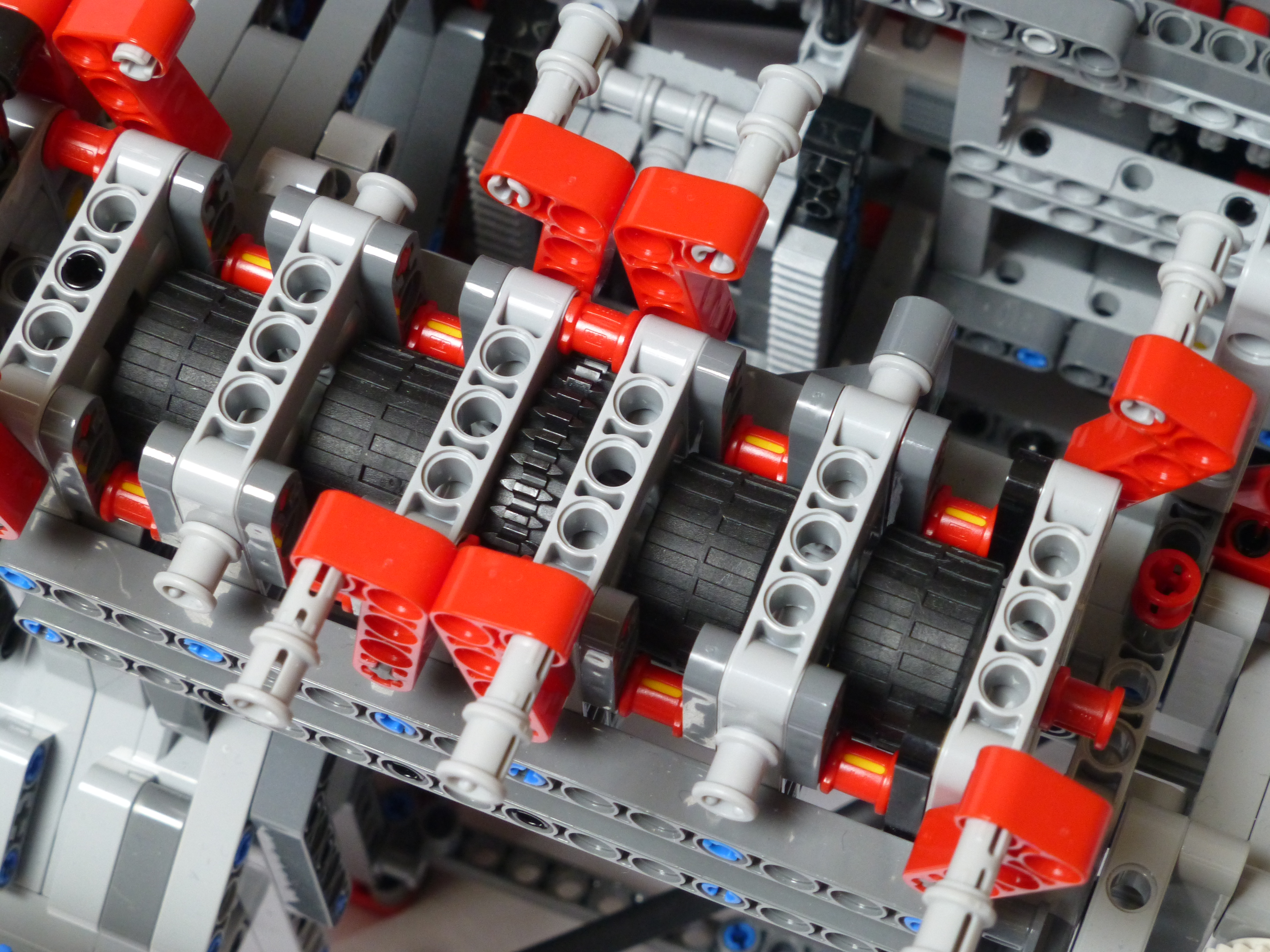
The solution to problem #1 was to build a complete replacement to the original thread tensioner. This time a set of 8 driven pinch rollers was implemented, along with a gearbox to control the warp thread supply drum.
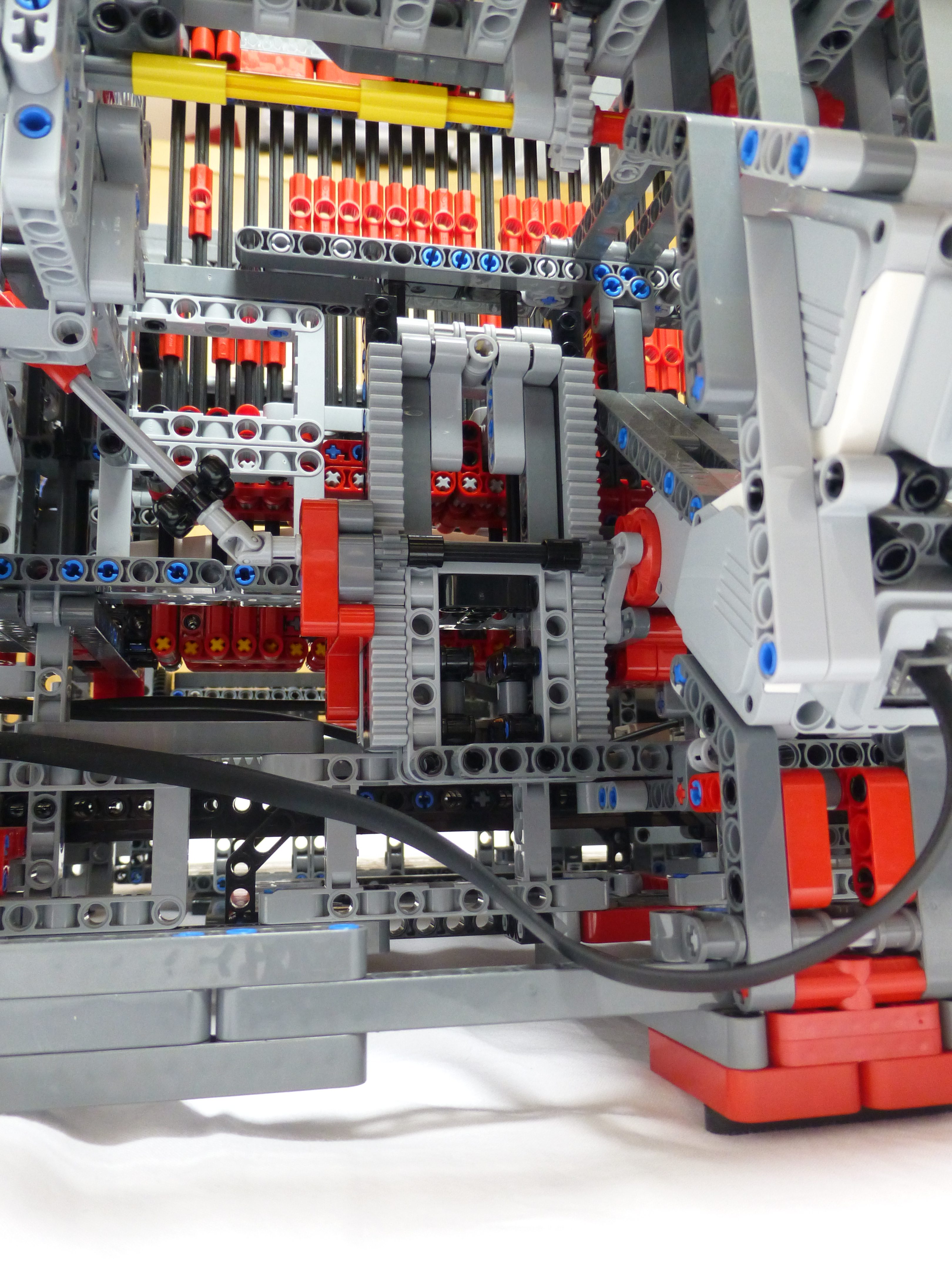
The picture above shows the new pinch rollers and the warp supply drum. There is a gearbox, shown in the picture below, that connects the drive of the pinch rollers to the warp supply drum.
When the gearbox is selected in one direction the supply drum rotates very slightly faster than the pinch rollers, with a white clutch gear for protection. This allows for much faster loading of the loom. The threads can be placed in the rollers and clamped down, and then tied to the drum. The loom can then be set to wind the threads up on the drum, with all threads at equal tension. Moving the gear to the other selection connects the drum to a gear on a blue axle pin. This simply applies some friction to prevent the drum from spinning uncontrolled as the loom weaves. Neutral allows for rapid removal of threads when needed.
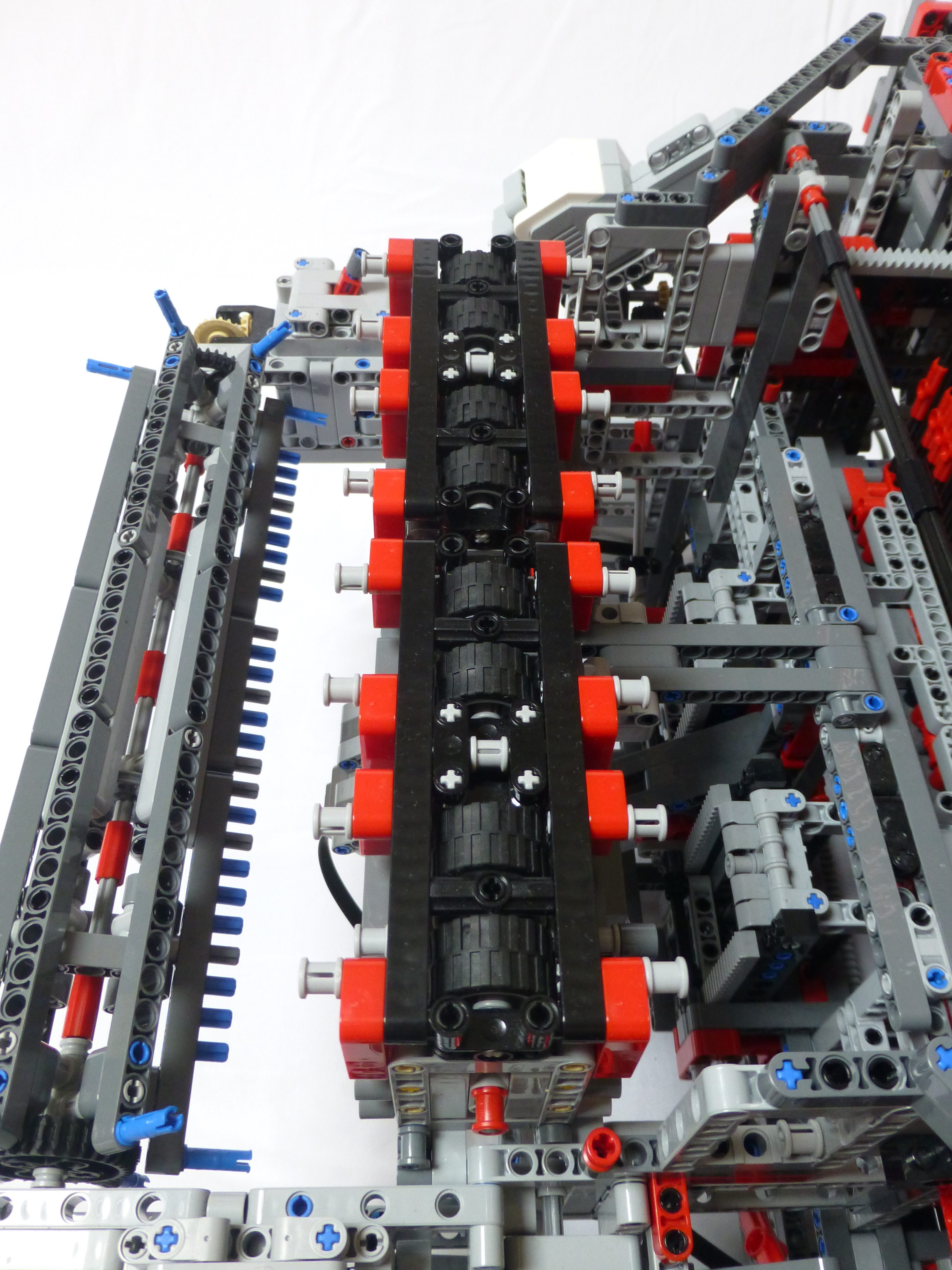
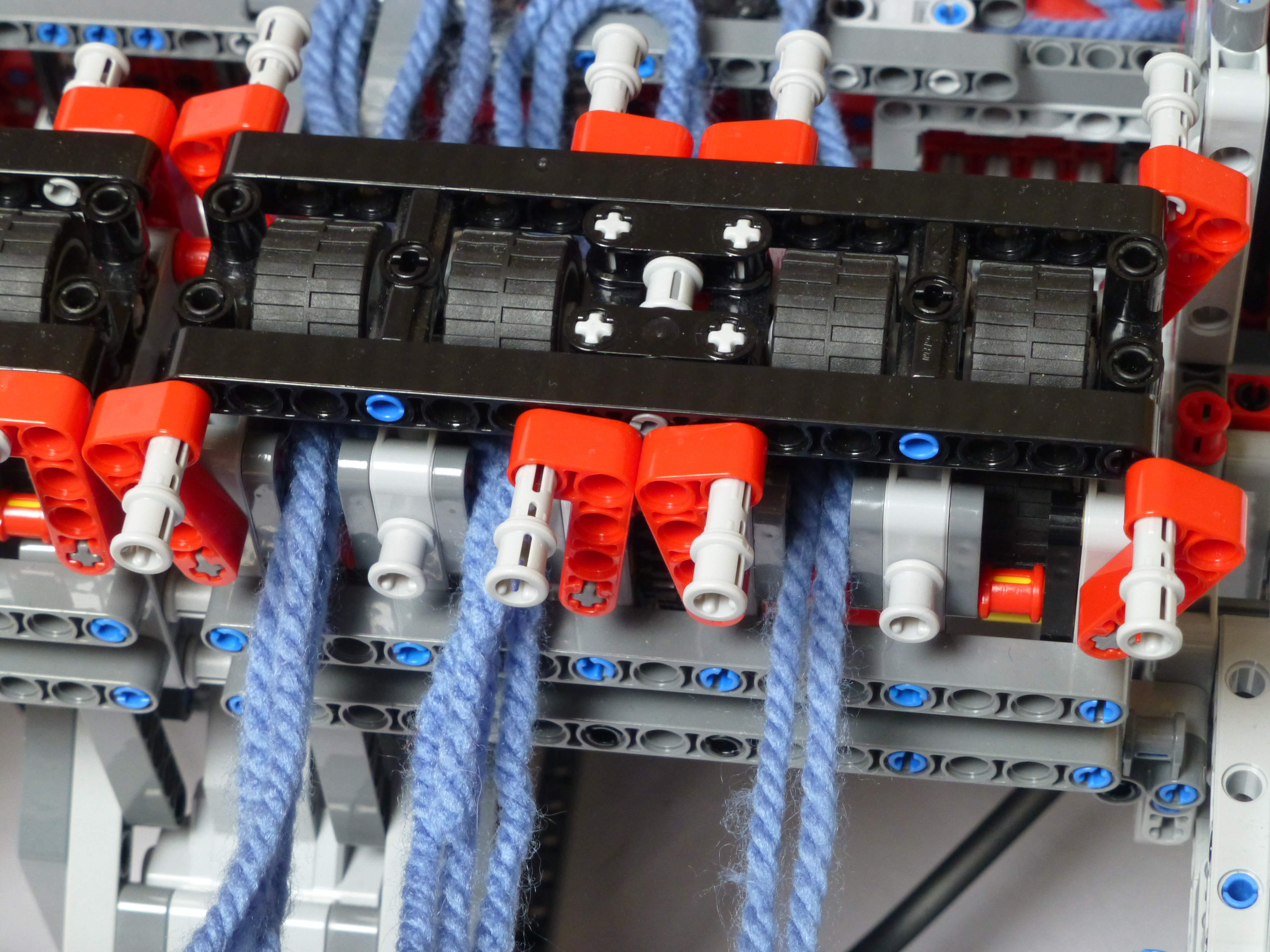
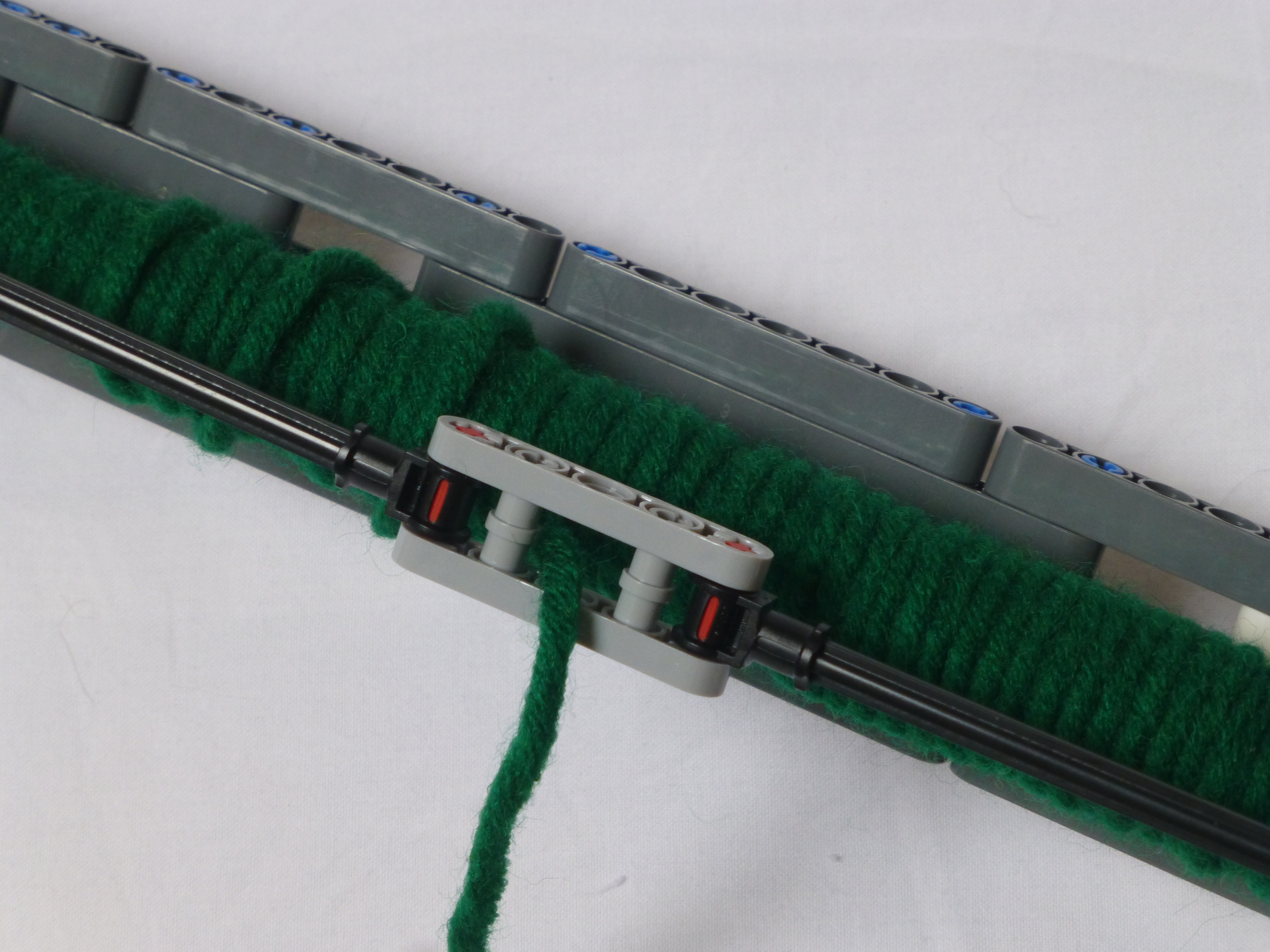
The lower pinch rollers, as shown above, are all driven by a large EV3 motor. When weaving, just before the heddles are lowered, these rollers will move the thread forward by one weft thickness (adjustable during operation), thus lowering the tension in the loom. Tension is restored when the cloth is wound forward on to the take-up drum at the front.
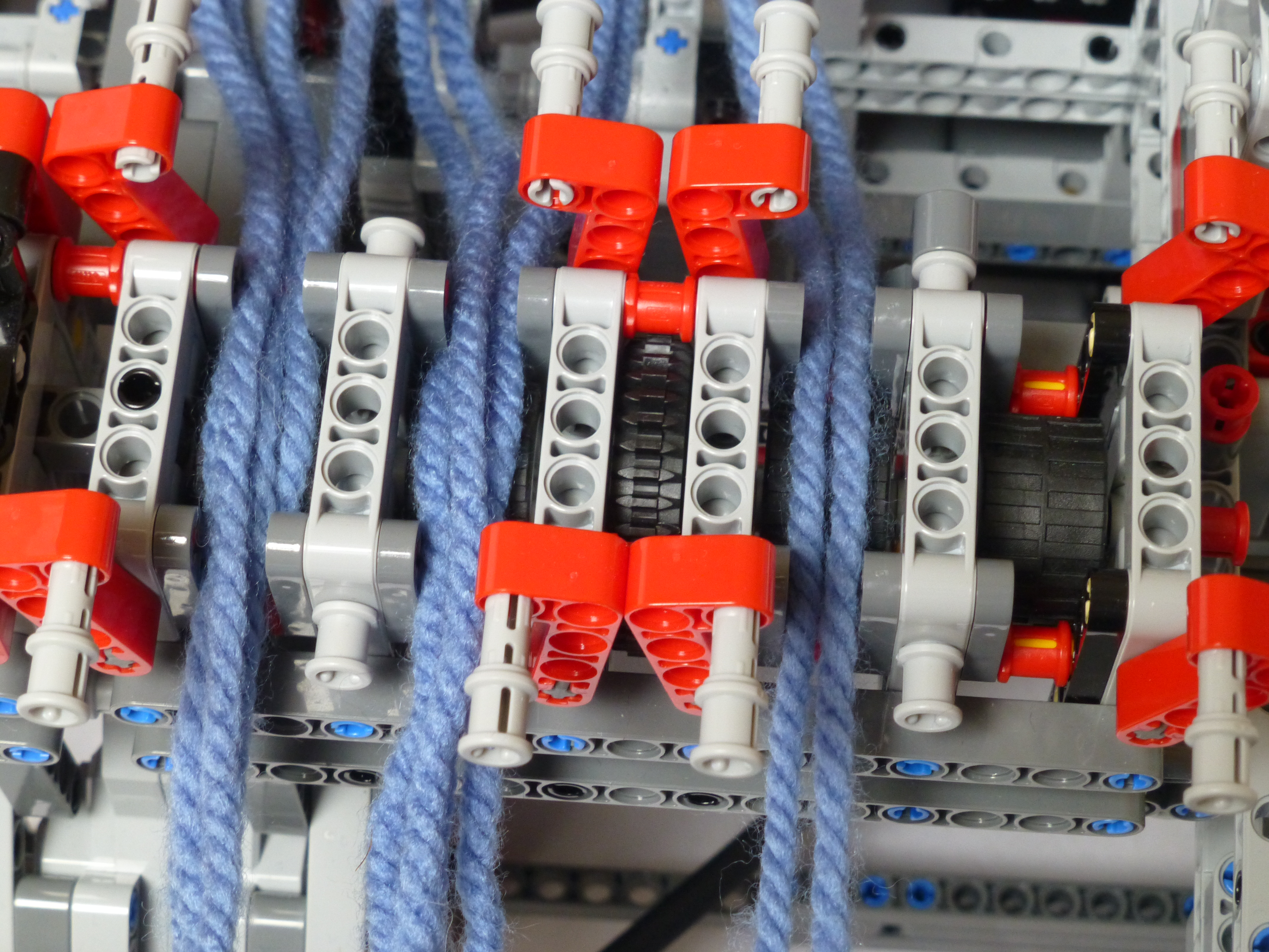
Loading the threads is simple – 4 threads per pinch roller, and then clamped in place with the top rollers as shown below.
Solution #2
Various solutions to the vibration problem were tried, most involving attempts to increase the sliding friction on the pins. None of them worked; no solution to applying just a little friction in a LEGO-only manner could be found. Instead, the simple solution of tilting the loom slightly forward was tried. This would mean that if the pins were to precess, that they would move forward rather than backward due to the slight slope. Raising the back of the loom up by 1.5M over a distance of 48M is just about 2°, so not a massive tilt, but just enough. The beams running under the loom, as shown below, give that tilt.
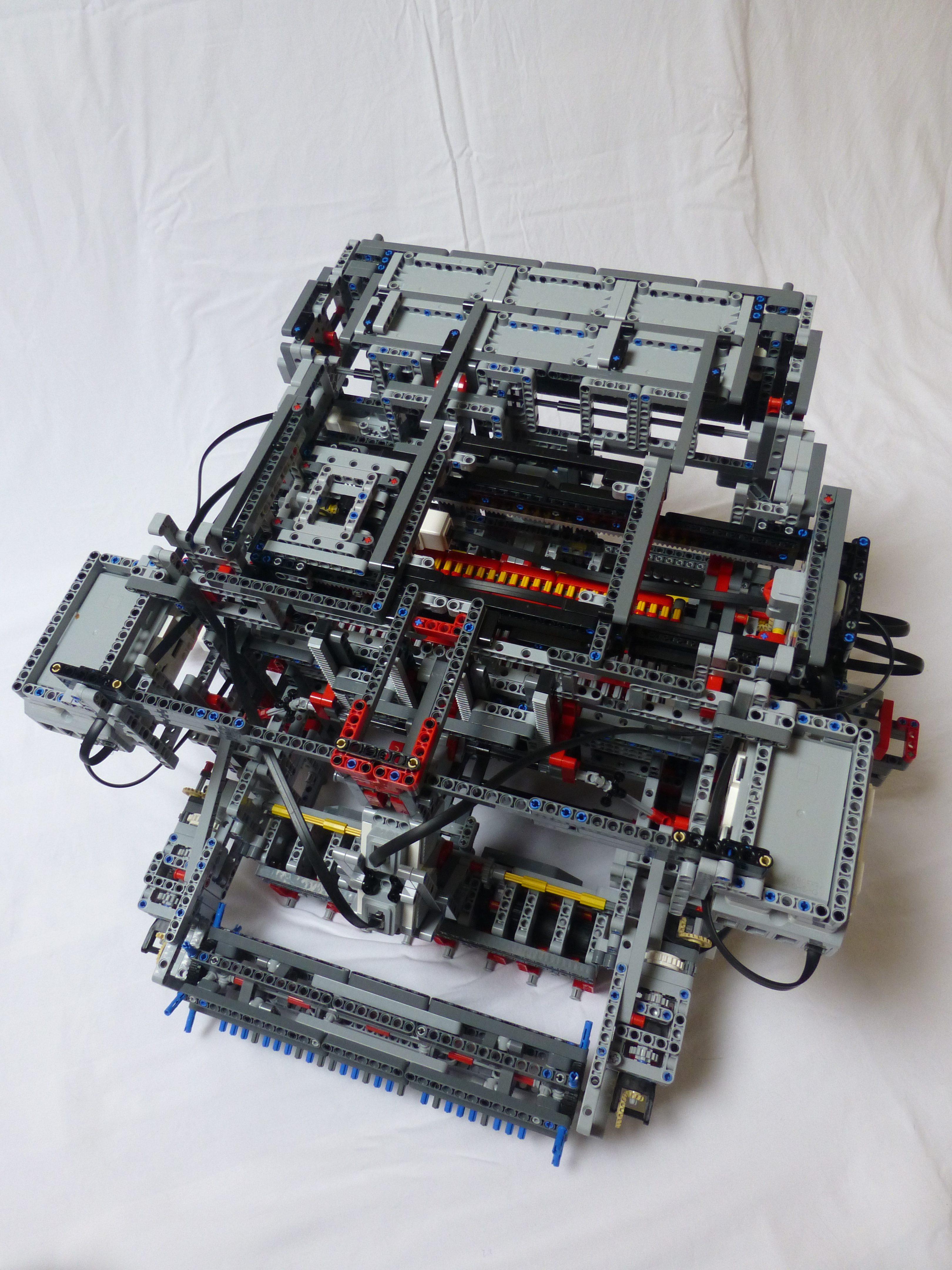
Photoshoot
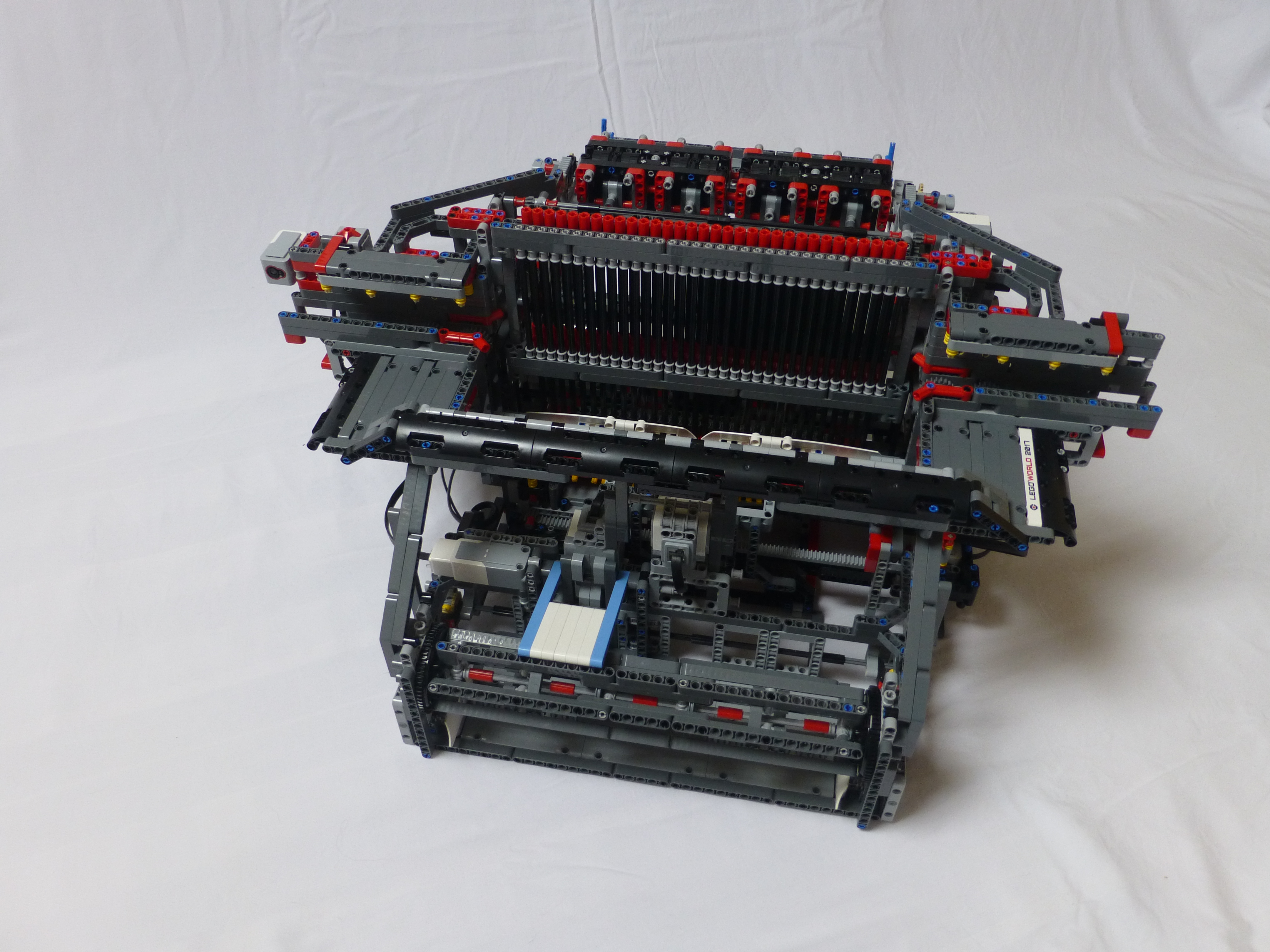
Whilst I was taking pics of various parts, I decided to take (hopefully) some good pics of the rest of it whilst I was at it. I include those below.
The grey racking at the front of the picture above has a partner rack at the back. This is used by the pattern setter to move left and right.
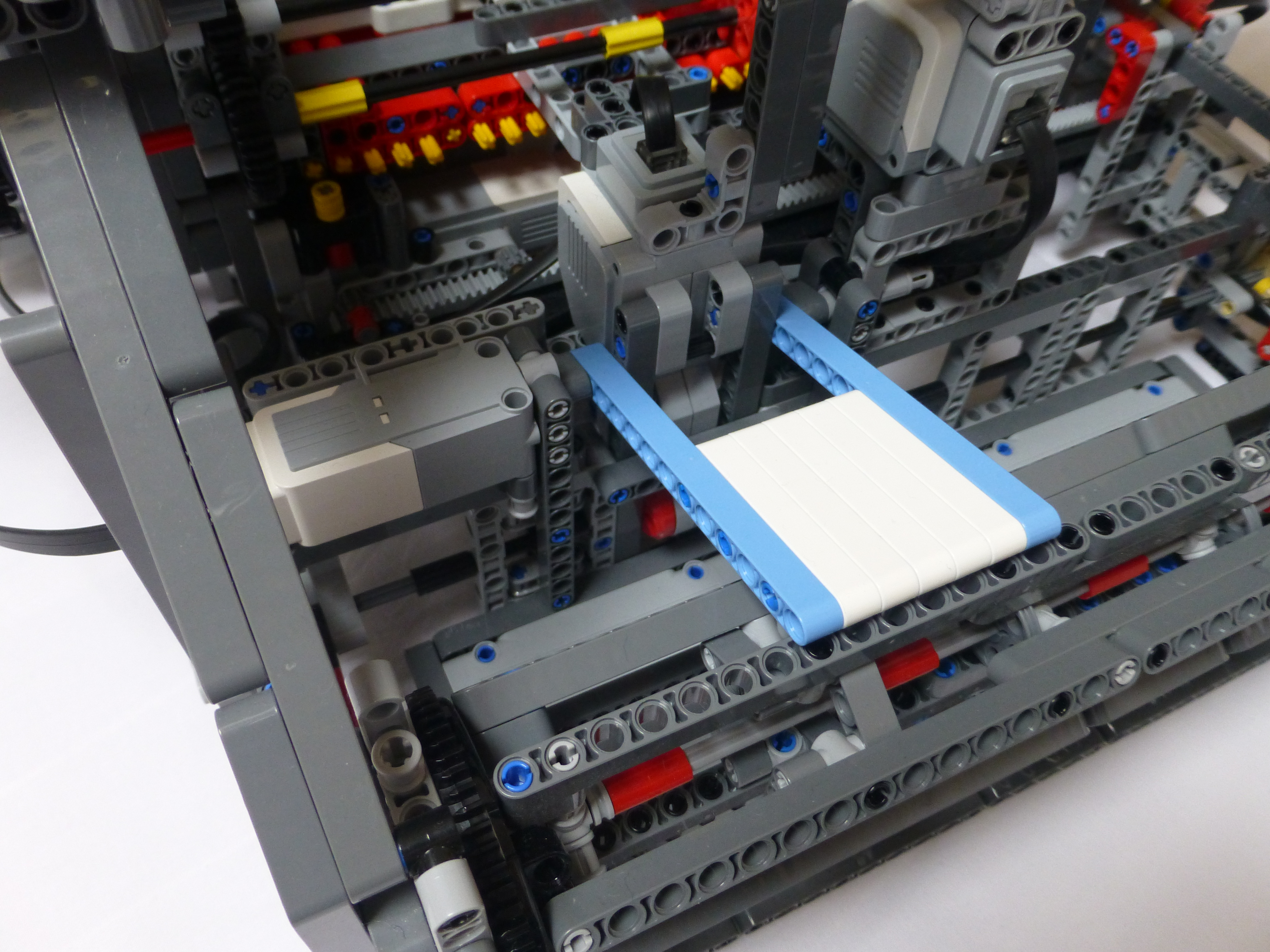
The white and blue flap above is connected to the medium motor. After each pass of the shuttle, the motor lifts the flap, and then lowers it gently until it stalls. The motor angle is then used to compute how wide the cloth take-up drum has become. That in turn is then used to compute the angle of rotation needed to ensure a consistent movement of the cloth, i.e. the width of the weft. This should be the same distance as the pinch rollers will move. The thickness of the weft can be adjusted during operation, along with minor adjustments to the drum and pinch roller positions.

The picture above shows part of the rear beam lift mechanism. There is an identical rack on the righthand side of the loom, along with lifting racks at the ends of the beam.
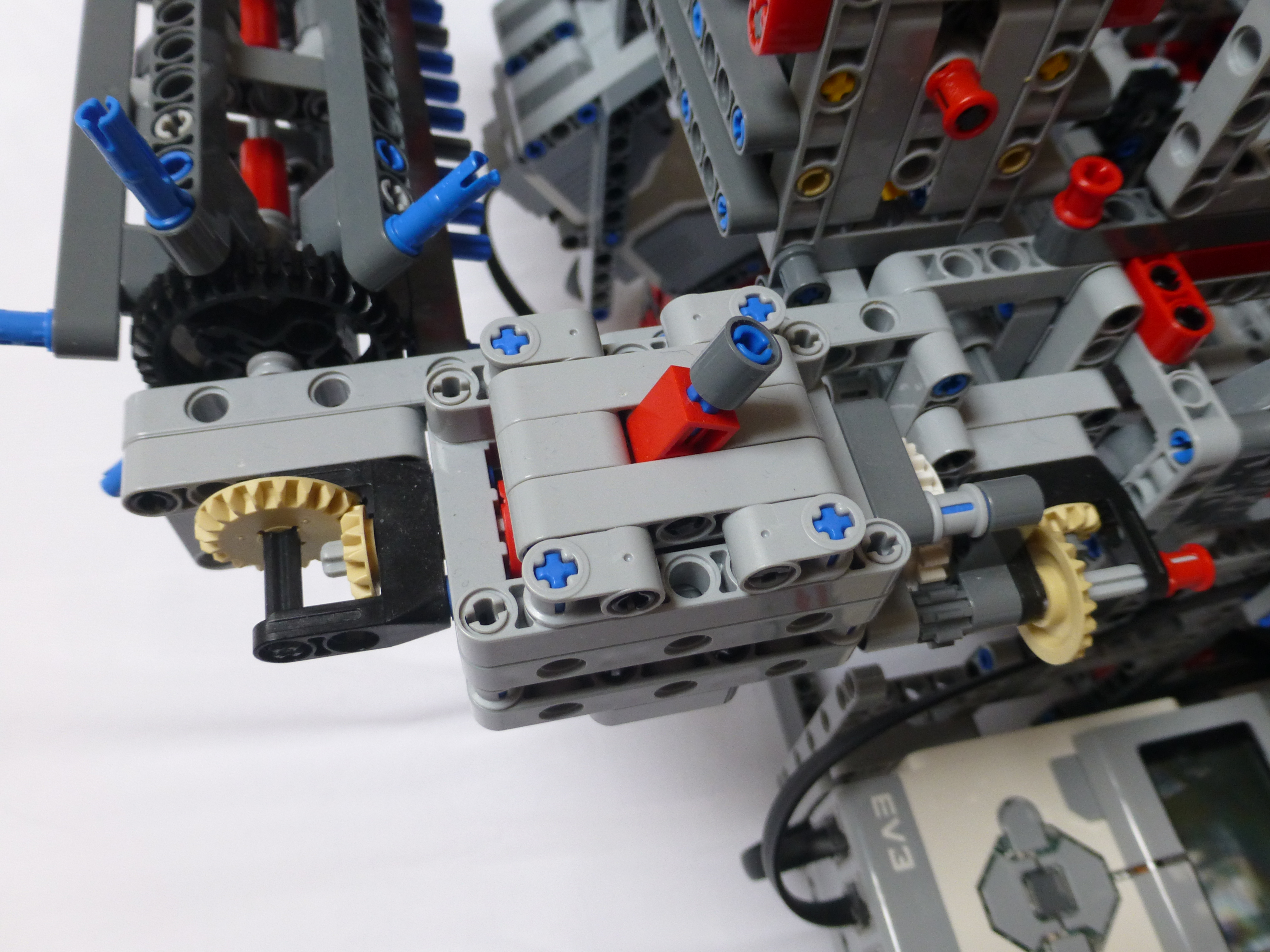
The light grey structure is the bottom of the pin setting mechanism. This moves left and right, under the pins, pushing the pins back and forth. It is programmed to set the pins in both directions, rather than returning to the ‘start’ on each shuttle pass.
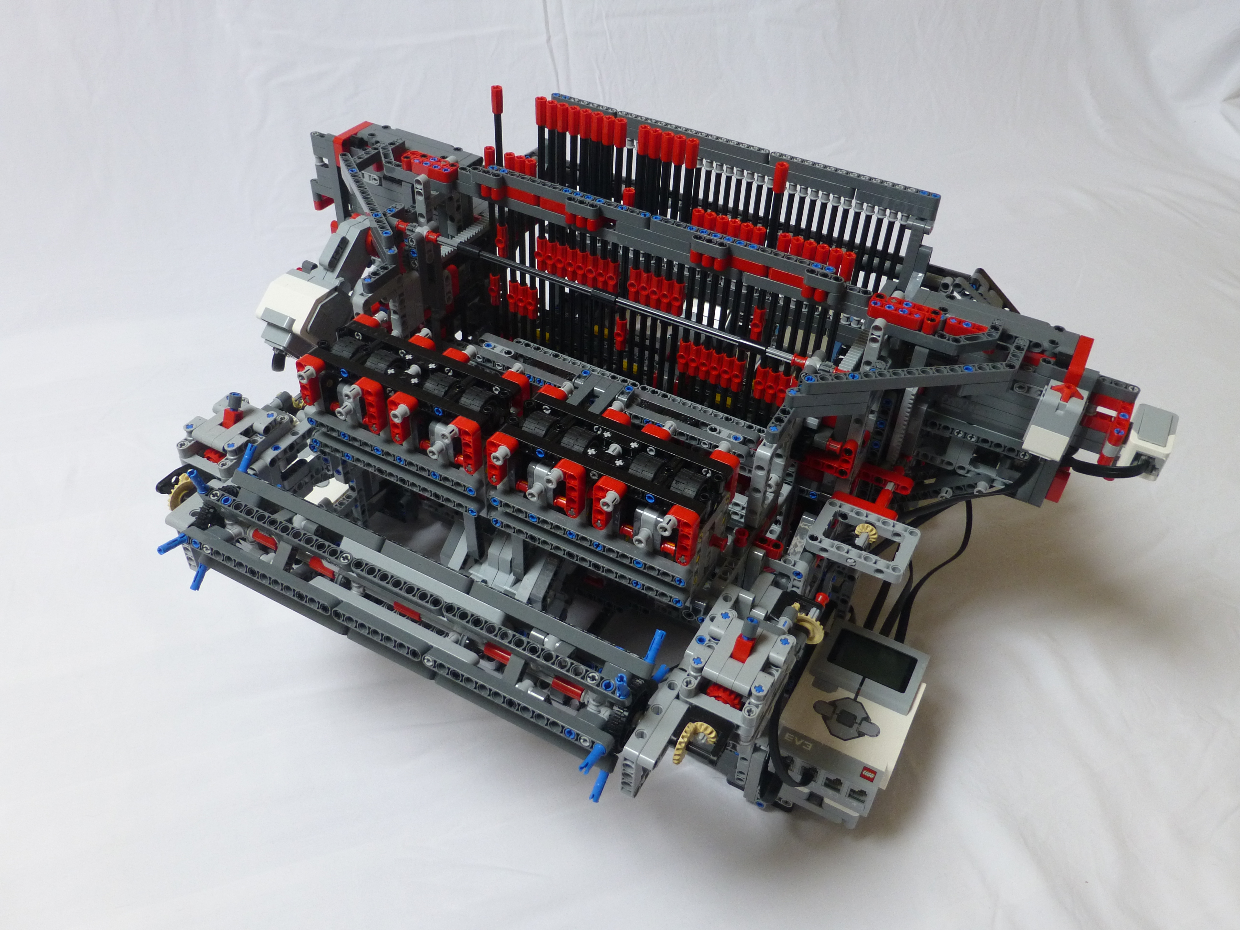
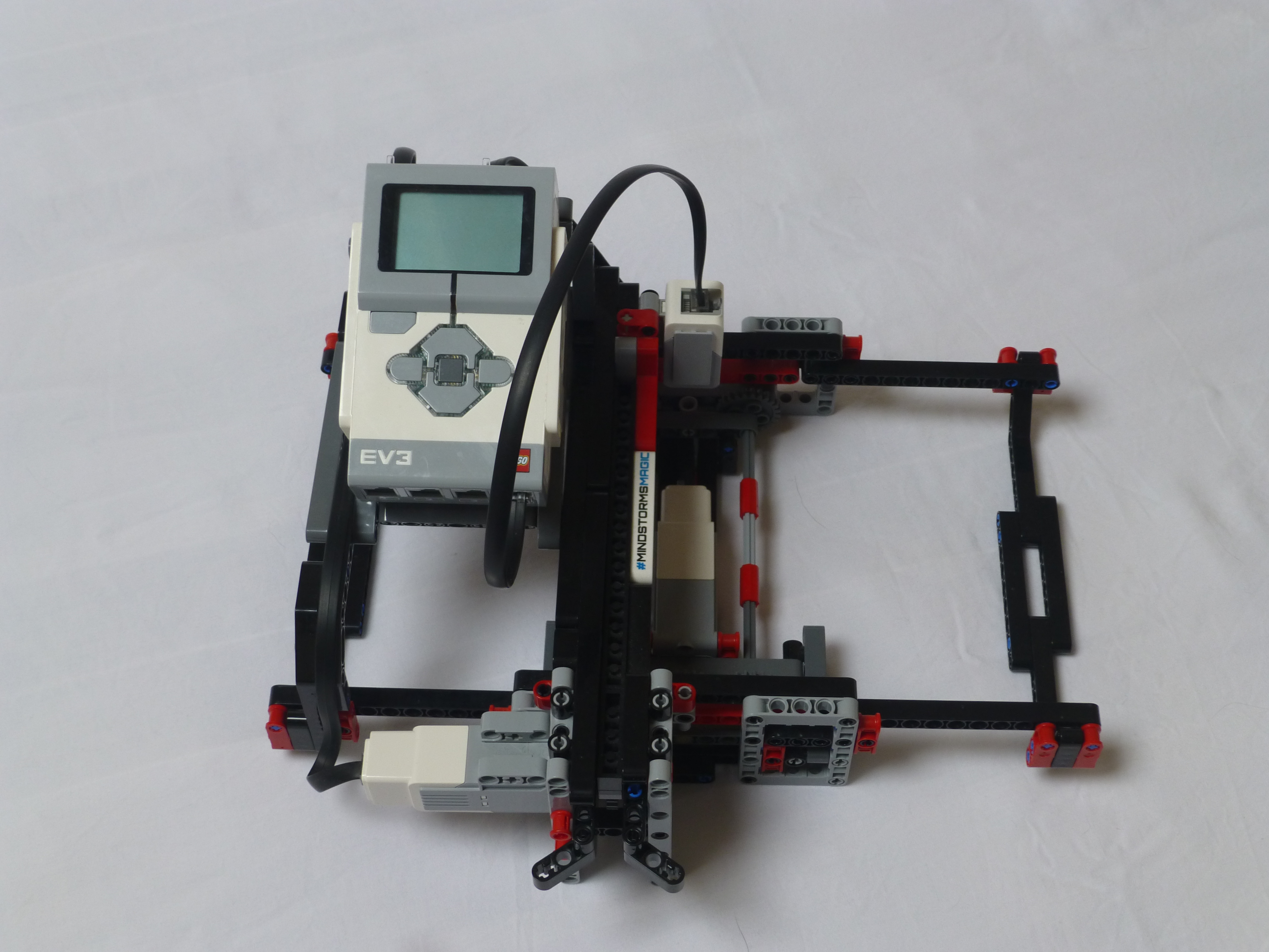
The entire loom is controlled by the EV3 shown above. Bluetooth is used to coordinate the actions of the other two EV3s. One EV3 manages the heddles setter (2 motors), heddle lifter (1 motor) and the reed (1 motor). The other EV3 manages the shuttle (1 motor), pinch rollers (1 motor), cloth wind drum (1 motor) and drum sensor (1 motor).
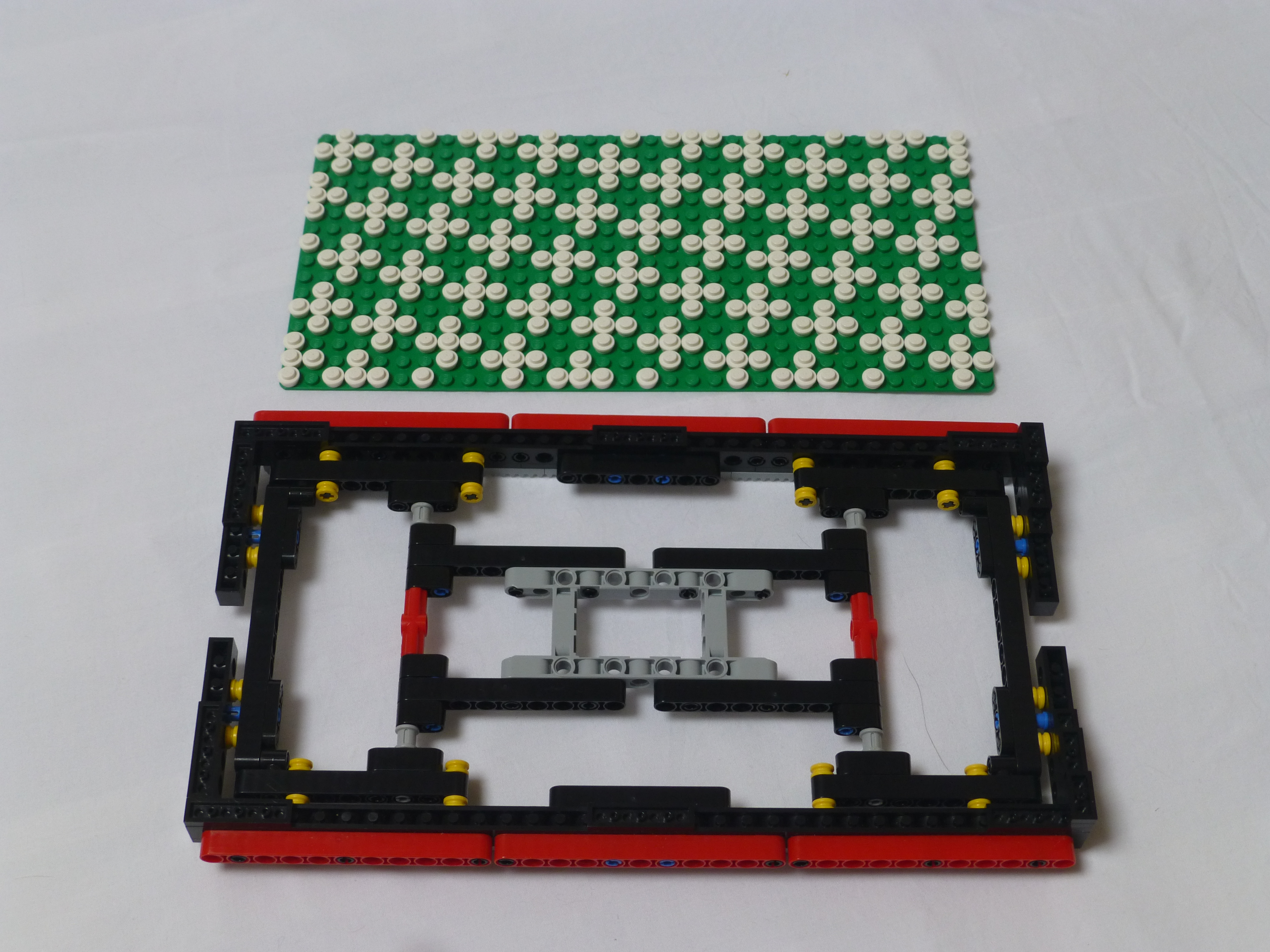
The pattern boards can be used to set up what to weave. They are 16×32 boards, with the pattern woven across the middle 16 warp threads, using 32 wefts. A plain “up, down, up, down” pattern will be woven into the 8 threads either side of the board’s pattern to ensure that the cloth remains in shape.
I’m hoping to take some videos of the loom in action next week and will post them to YouTube.
Wow. Just wow. I love how you solved everything mechanically, with the clutch gear and the blue pine and tilting it. This build is incredible. I enjoy the photos the most. I felt I was understanding and solving the problem with you. Congratulation on your solutions and your observations.
It was great to see your various machines at Monkey Bricks last weekend and it would be awesome if you might be able to bring a selection to the Calder Valley Brick Show (www.brickshow.co.uk) on the 27th January 2019 in Mytholmroyd.
Would it be possible to get the design files for this, the links you posted dont seem to work. I want to work out the basic structure of this loom and then produce a non lego version of it with an SLS printer. One thats capable of printing woven tags for clothing.
So how are you loading the patterns? Are you reading .WIF files, or hard-coding a specific pattern?
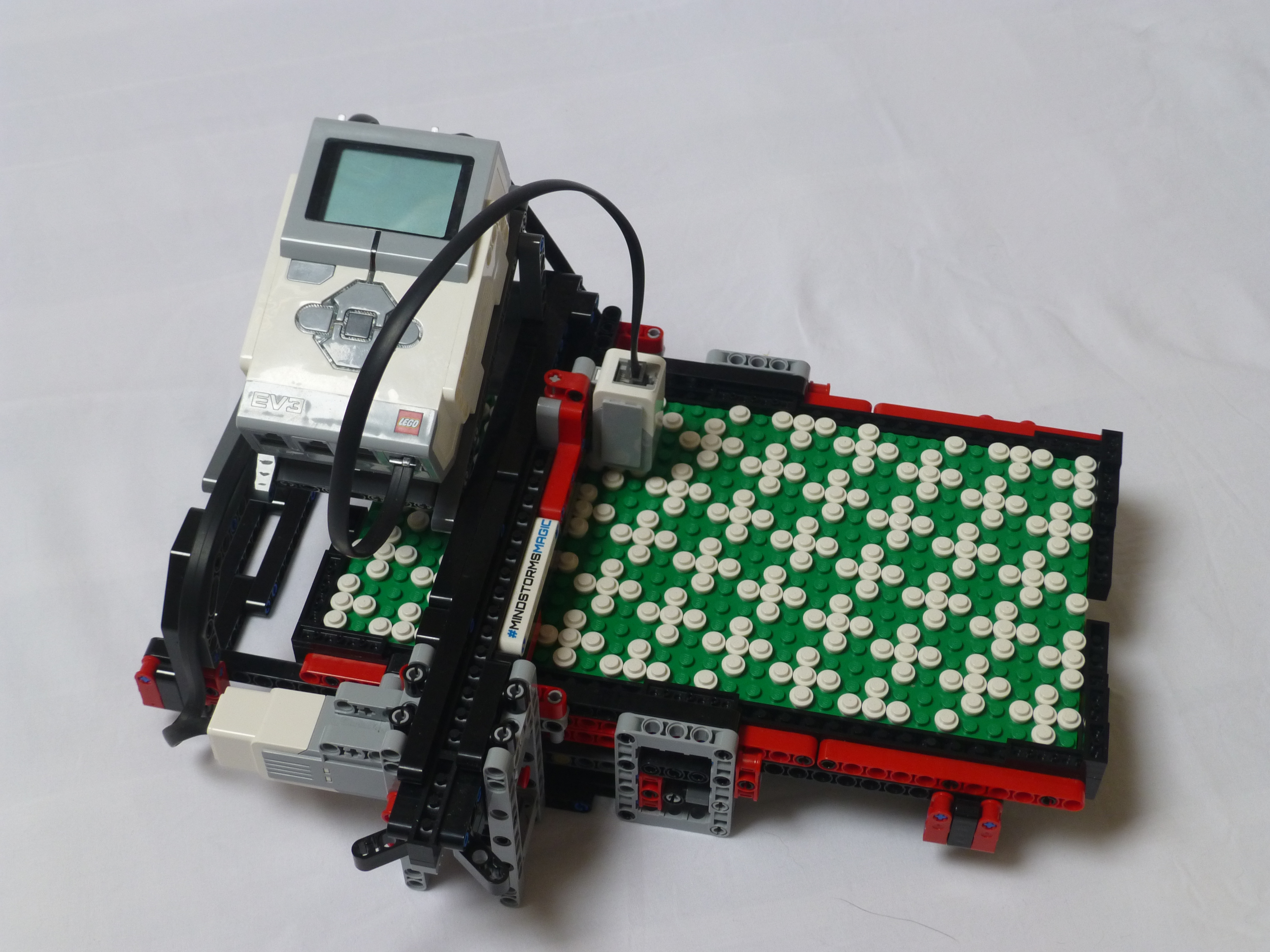
If you look at the end of this post, you can see the pattern boards – the 16×32 green baseboards with the white 1×1 plates. Those define the patterns – very much like the punched cards of a Jacquard loom. The main EV3 scans those boards in, optically, and then transmits the pattern to the other two EV3s on the main body of the loom. The controller EV3 can also store the patterns for future use, so it doesn’t have to scan the boards every time.