Well. The loom is a very complex model and a lot of it was built on-the-fly as it were. I kept changing things on the original design, back in 2016 (!), until it worked – well, worked enough. A lot of that, understandably, was right on the inside of the model. To make BIs (build instructions) of that would require taking it apart – which was a very scary thought. So, I basically avoided doing that for as long as possible. Since the loom worked, I didn’t want to risk it not working again after being taken apart.
I showed the loom off at Brickstastic ’26 this year. Unfortunately, on the first day, one of the large motors died. You can of course guess whereabouts the motor was. Yup, right inside. It was the heddle lift motor which, to be fair about it, has the hardest job and had done a lot of scarves in its time. It took me about 15 minutes, kneeling on the floor, to extract the dead motor and to swap in a spare – which I had fortunately decided to take with me. Over the past 2 years I’ve had 4 large motors fail on me in various robots, so I was concerned that another might fail.
Given that I’d had this failure, I was concerned about the other motors. So I figured it was time to bite that metaphorical bullet and give the loom a good clean, swap out any stiff motors with my spares, and take the opportunity to make the BIs.
A quick aside about motors
Thankfully I had a few spare motors in. Initially destined for a possible knitting machine which, according to my current thoughts, will need 15 motors! Having had 3 motors fail, before this one, I’ve been investigating options for repairing them. The large motors are actually relatively easy to take apart. The brass gear on the motor does need a blow torch, a catering one works, to remove as it’s an interference fit. The issue I’ve found is getting new DC motors with the correct speed. That hunt has failed me so far. I did succumb to buying some clones from AliExpress and, apart from cheaper feeling plastic, they do appear to be good alternatives. The speed is correct and they’re a little quieter than official ones.
Back to Build Instructions
Over the years I had already made models for parts that I had either replaced or added, e.g.
New cloth winderWarp thread tensionerBobbin frameBobbin frame supportNew head / scanner
Making the rest of the model has been a labour of love. It’s taken me a couple of weeks of working out how I can pull sections of the loom, and then modelling them.
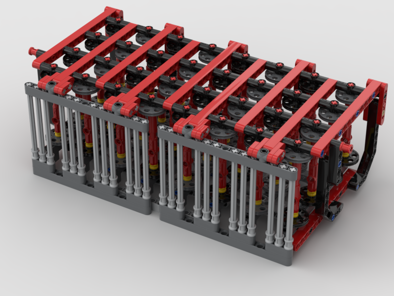
Cloth Support BarThe ShuttleUnderside of the Pattern PinsThe oldest part of the loom – the Pin Setter
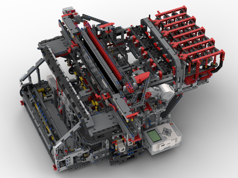
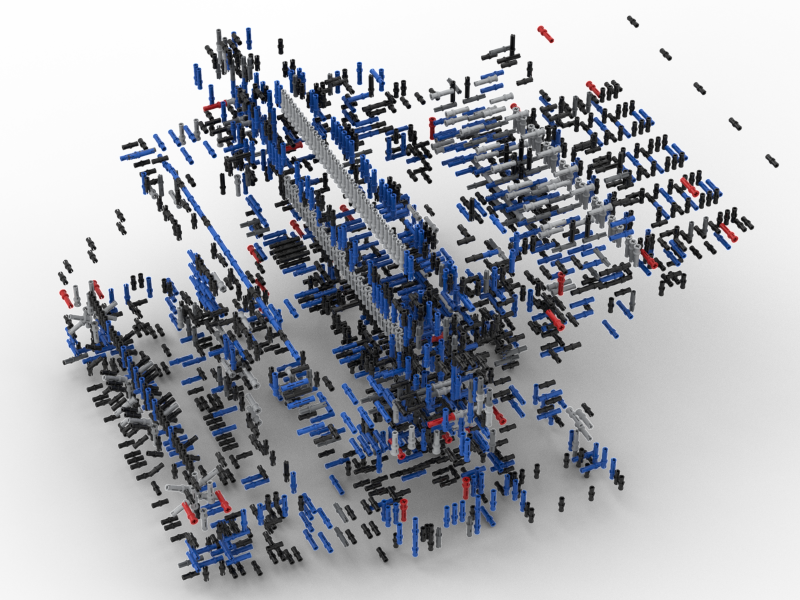
What has amazed me is how many parts are in this loom. I’d always thought it was a couple of thousand or so. I was so wrong. There are 5,659 parts in the body of the loom alone! There are a further 590 parts in the scanner. What then amazed me more is that 40% of the part count is connecting pins, 2291 one of them.
For fun, I have also rendered the above as a rotating animation:
The Bad News
Sorry folks. After putting all this effort in to making the BIs, I’ve decided that they’re currently just for my benefit. I like the fact that this is a unique model and that there is only one of it in the world. The BIs are rather complex and I made the decision that some sub-sections would actually require a bit of dismantling to get into place as it made the modelling easier for me. The other issue is that the loom is programmed in EV3g, which will be hard for many to find the application for.
What I may consider is releasing a “single step” LDraw file with all the parts in the right places so others can at least look at it as a model. I’ve not yet decided on that.
The Future
Now that Pybricks supports the EV3, I am planning on re-writing the whole system using that. I can’t really start on that until Pybricks supports Bluetooth as there are 3 EV3s in the model that communicate that way.
Maybe, when it is in Python, I might re-consider my thoughts on sharing the BIs. I’m still not sure on that though.
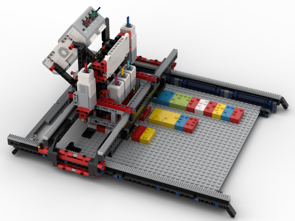
A little over a year ago I designed a Braille Bricks reader. I was pleased with how that came out, until I tried to demonstrate it at a show. It was struggling to accurately read the boards. After some thought it became clear that the whole structure was too flexible and the table at the show was uneven which was causing the problem. Since the bot moved over the entirety of the board, there could be variations in height of the bricks causing the misreads.
Redesign
For various reasons I didn’t tackle the issue with the misread for several months. When it came up to the next show I still hadn’t tackled it, so I decided that I’d revisit it after the show.
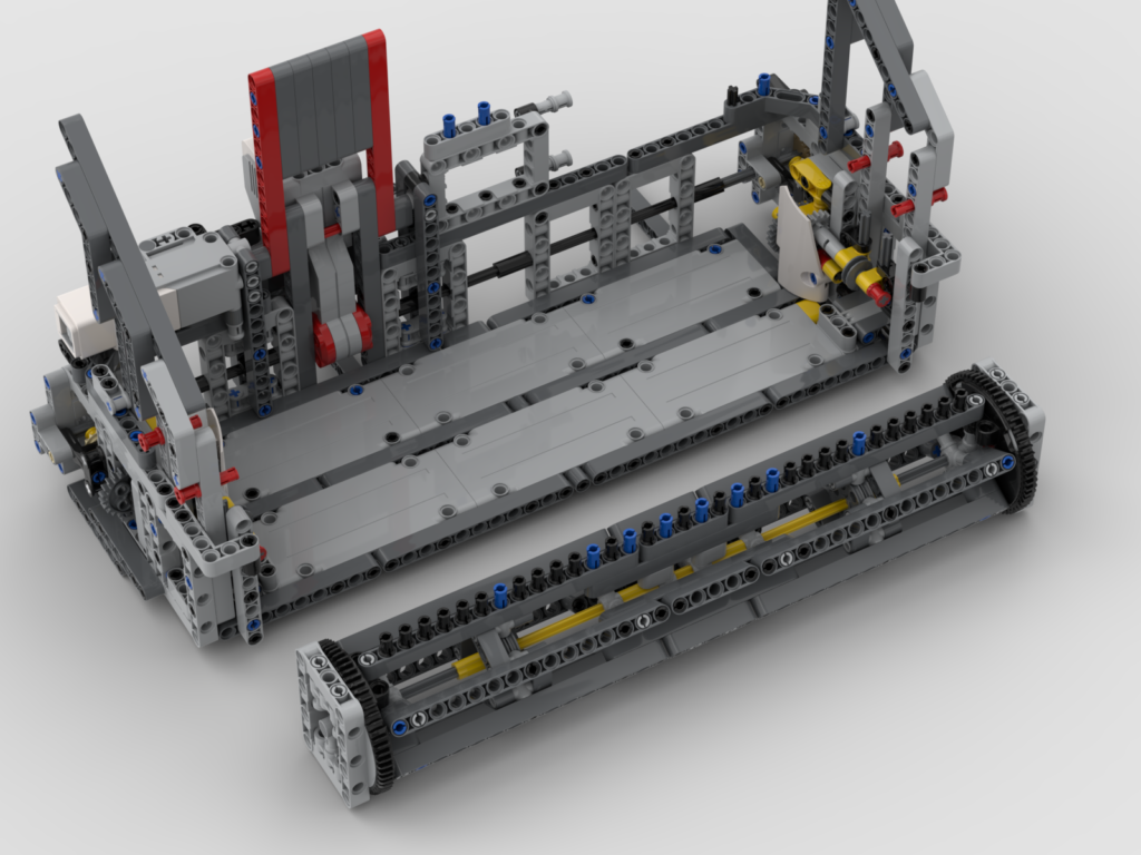
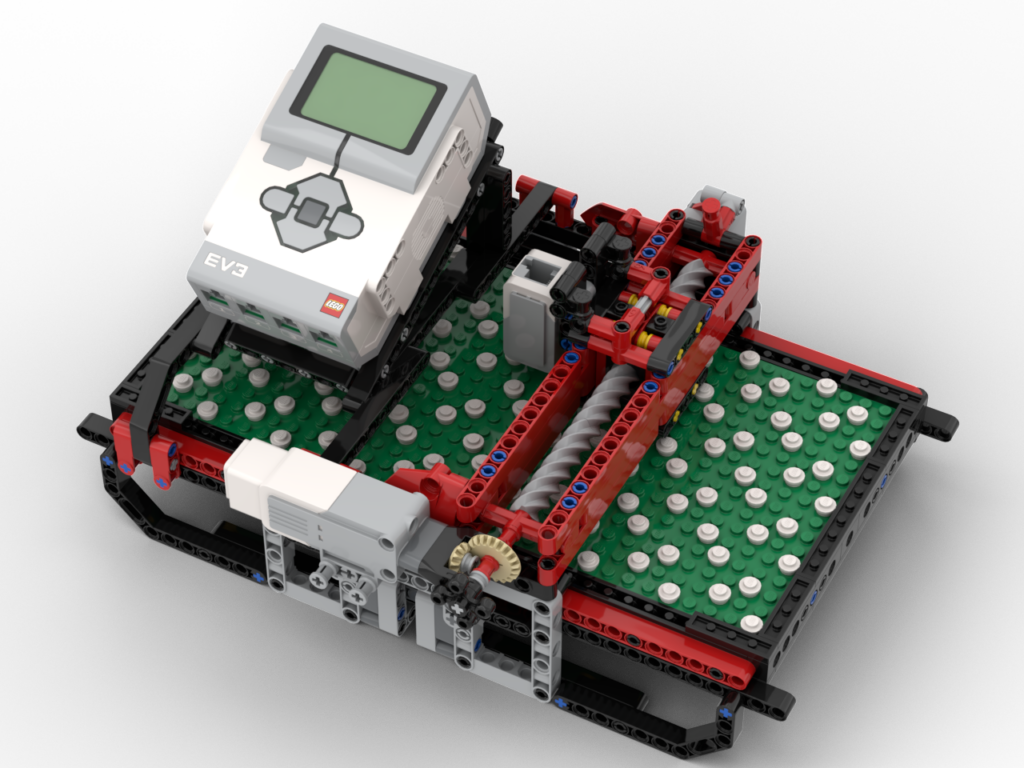
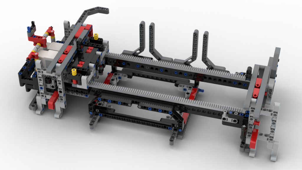
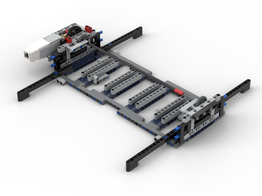
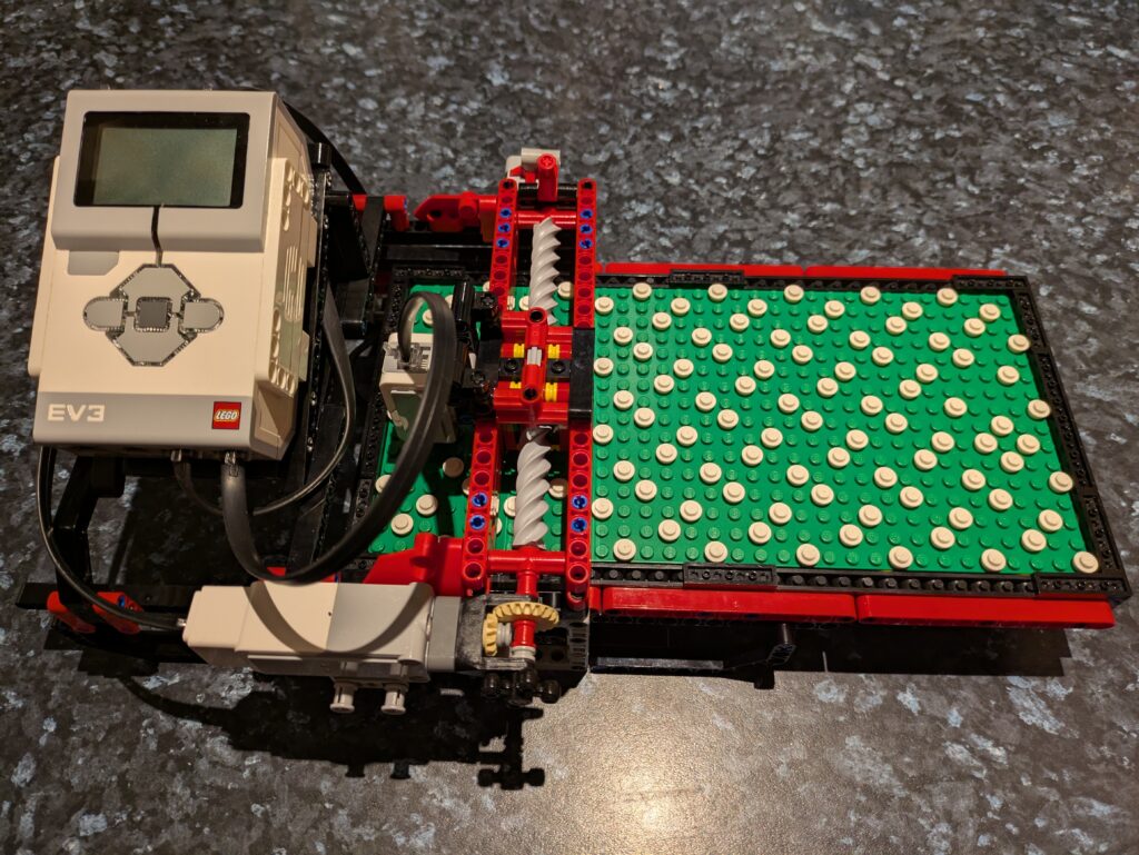
To make things sturdier I decided that the bot would stay in one place (whilst reading) and the board would move underneath it – in a very similar manner to my loom’s pattern scanner. This would allow the ‘bridge’ structure to be stronger as it would be anchored properly underneath and, also, a consistent support under the board. It does, however, mean the bot needs more space to operate; the original one needed ~40L horizontal space vs ~66 for the Mk2. I think that’s acceptable for the purposes or showing.
(Re)Coding
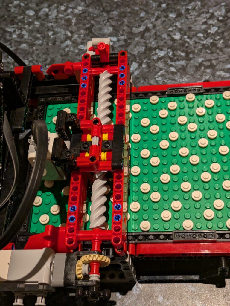
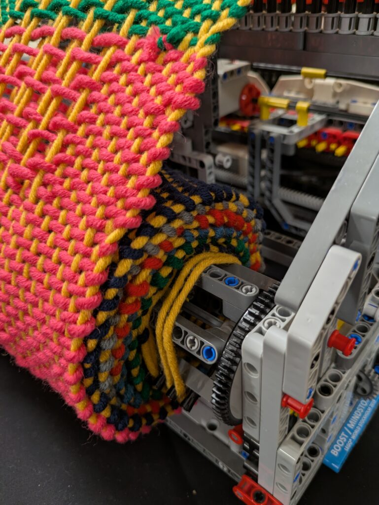
When it came to recoding, I was rather fortunate. The original design used a 1:1 gear ratio driving an 8T gear to move the board. This one, to resist gear skipping, uses a 24T gear, so I’d need to down gear 1:3. By fluke I’d decided to reduce the load on the motor by using the 12:36 gearing (visible in the pictures above), so ultimately it was still a 1:1 gear! All I needed to do was change the direction of the motor which is easy to do in Pybricks on ev3dev.
I also needed to tackle the ‘touch’ sensing code. The original design’s ‘bridge’ would sag, which meant the ‘finger tips’ were closer to the board than on the redesign. This had a knock on effect that the test for a column with no studs could fail and be detected as no brick present, i.e. a space. All that was essentially needed was to extend that range a little along with some other logic changes.
Recently, whilst working on my Braille Reader rebuild, I decided that it was time to investigate options for an external speaker to increase the volume, as the onboard speaker is rather quiet.
Bluetooth Speaker
I’d seen that other people had managed to get Bluetooth speakers working with ev3dev and Pulseaudio, so since I had a BT speaker lying around I thought I’d give it a go. Unfortunately it wouldn’t connect. The EV3 would see it, pair, but any attempt to connect resulted in a Bluez error. It was an old speaker so I decided I’d get a new Anker (I’m a fan of their stuff) one, which would also see duty with my bat detector as well. That also didn’t connect. I’m guessing that the EV3 wants to use a rather old protocol that neither of my speakers supported, which is a shame.
USB Audio
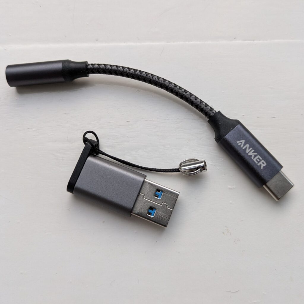
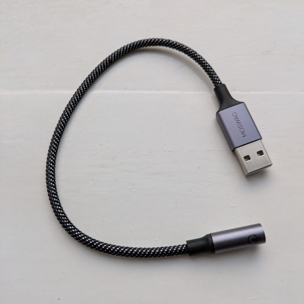
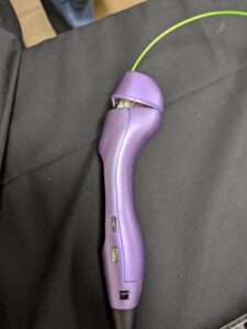
Not one to give up on using an external speaker I wondered if USB audio would work instead. When I changed my phone, I ended up buying an Anker USB-C to 3.5mm headphone DAC:
I did need to use a USB-A to USB-C adapter, but it worked. It worked really well, on the whole. Using USB alone didn’t require Pulseaudio to be installed once I’d set up the .asoundrc file in ~robot:
defaults.pcm.card 1
defaults.ctl.card 1
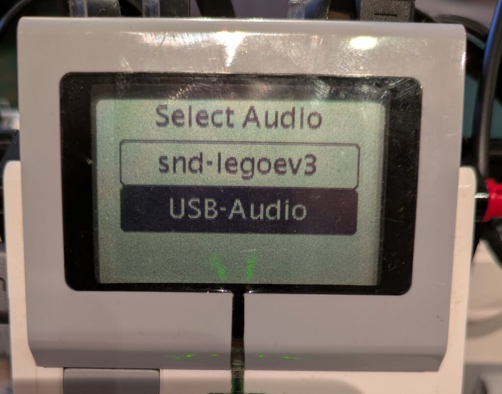
The downside to using .asoundrc is that if the USB adapter wasn’t plugged in, there’d be no output. So I decided I write a little audio configure function that could be called at the start of my program to detect if there were any additional audio outputs and present a menu of choices, defaulting to the current one in .asoundrc:
If only the onboard audio is available, no menu will be shown and it sets the .asoundrc to use device 0.
Issues
So that I didn’t need to use the USB-A to USB-C adapter I did buy a USB-A audio device:
I wouldn’t suggest using that one. It’s very, very, quiet and the audio quality is poor. It glitches and, worst of all, it chops off the beginning of any sounds played to it which, given I want to use it for speech output, isn’t useful. The Anker unit is just so much better: louder, smoother, and plays the entire sound.
The other issue I came across is that using the ev3.speaker.say(…) function would often crash. It appears that the EV3 isn’t powerful enough to manage sending USB data whilst generating speech via espeak and sending that on to aplay. My answer to that is to manage all that in my own code and temporarily write the speech output to the /run/user/1000 tmpfs directory – that way it won’t damage the SD card:
    def Speak(self, text, filename=None):
        if filename:
            play = False
        else:
            filename = "/run/user/1000/speech.wav"
            play = True

        os.system(
            "espeak -a {} -v {} -s {} -p -w {} '{}'".format(
                self.speech['volume'],
                self.speech['voice'],
                self.speech['speed'],
                self.speech['pitch'],
                filename,
                text
            )
        )

        if play:
            self.ev3.speaker.play_file(filename)
The code above accepts a filename as, for the Braille reader, I pre-generate some cached text prompts.
Utils Code Library
I’ll blog separately, but I refactored all the code that was used to generate the device selection menu et al into its own package so that I could release that. Hopefully it’ll be useful to someone else.
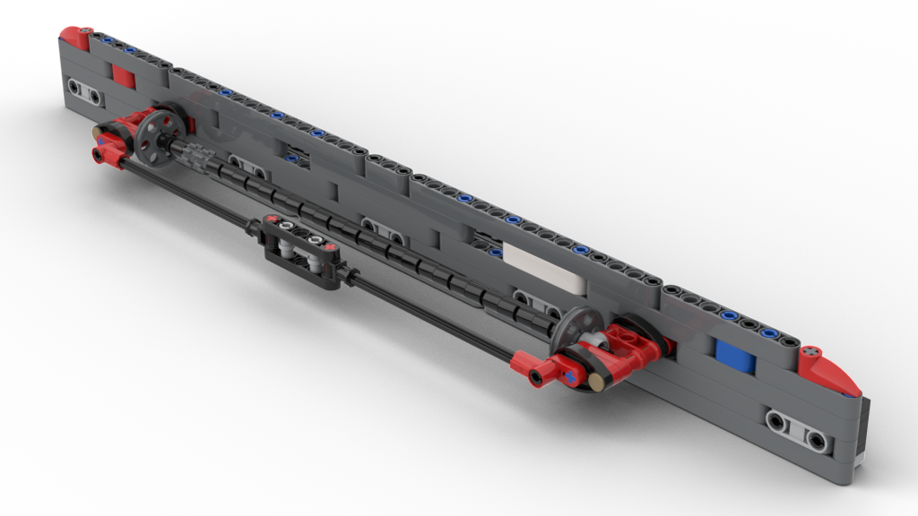
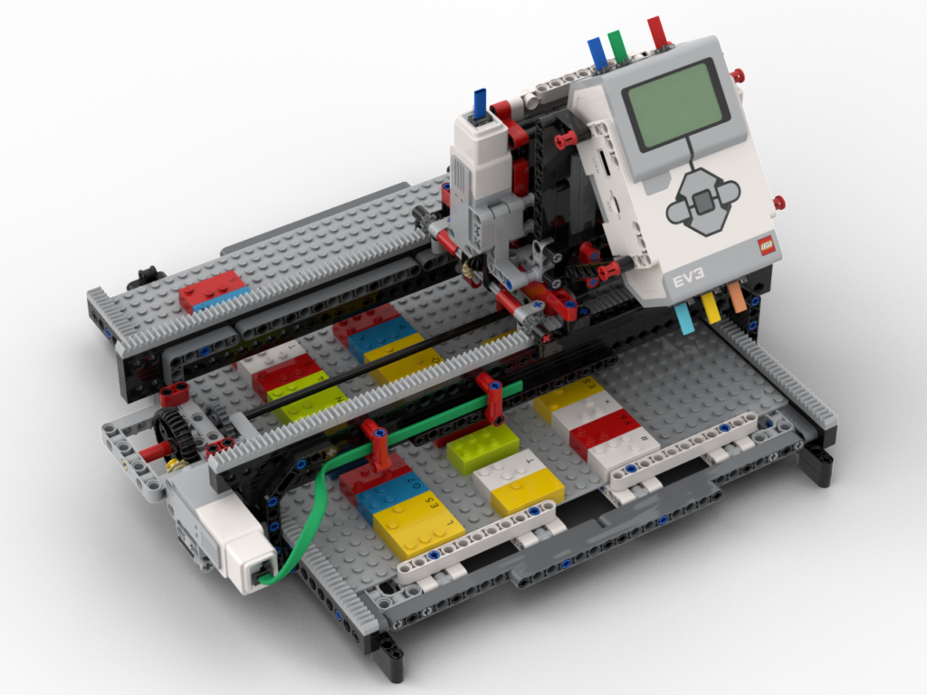
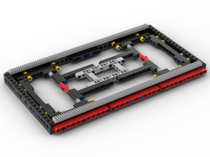
My redesign of the pattern board scanner part of my loom is basically complete. As it currently stands it’s a standalone scanner. It works ! It’s much faster than the old system and is really clean in its operation. I need to retrofit the new code into the loom controller code, which I’ll do in a few days’ time. Before that I want to deal with how the unit will sit on top of the loom, so I need to put the loom back into its operating state and get thinking.
Releasing the BIs and Code
Since this is working as a standalone device, and I’ve posted about it a couple of times on Facebook:
I’m, as usual, going to post the BIs and code for public use. I’m licensing them under the Creative Commons Attribution-NonCommercial-Sharealike 4.0 International licence CC-BY-NC-SA 4.0
There are no cables in the BIs – they’re a pain to route so I’ve left them out. The cabling ports and cable lengths are in the BIs. Routing them is left as as challenge to the builder 😉
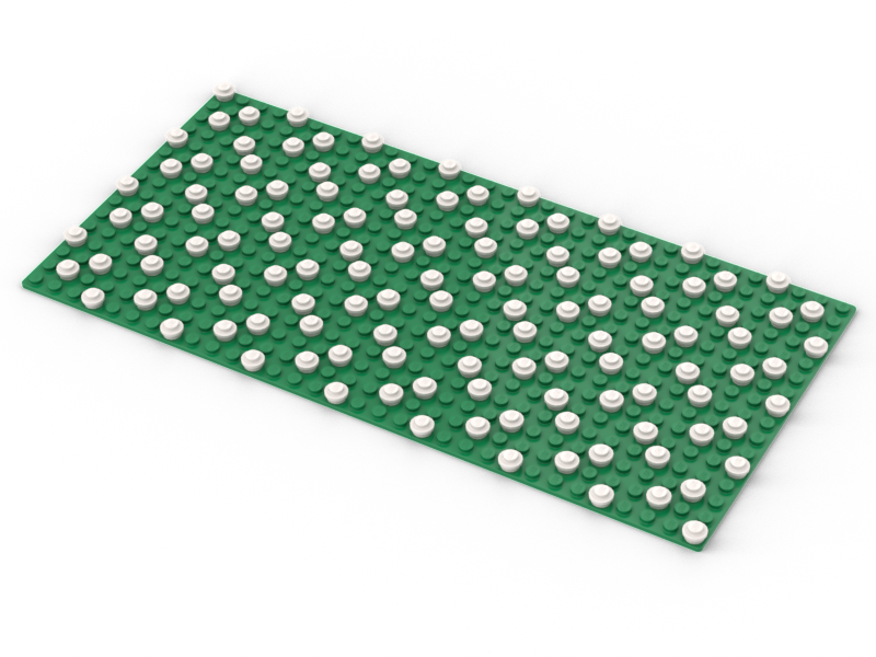
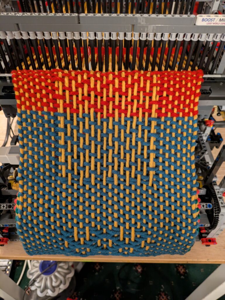
The code will scan a board showing the dots as it goes, then clear the screen, and reshow the code from the scanned data. This can then be used as a base for something else.
The past few times I’ve shown my loom at LEGO shows I’ve not been completely happy about the scanner / head unit. In the original build of the loom it was actually attached to the loom itself, so obviously part of it. Later revisions made it a stand-alone unit, which is good for showing it to people but visitors usually don’t realise it’s part of the loom.
At the most recent show, the scanning mechanism wasn’t working correctly. It’s not needed for the loom to work, as I wrote the code such that I can save good scans and re-weave them from memory. That’s useful at a show as it means I can keep the loom running without the 5 or so minute gap it requires to scan. I’d only scan when people were actively interested in that.
Time for a rethink !
There were two main things I wanted to do with the rebuild:
Have the scanner sit atop the loom, but still have it detachable.
Make it faster and more compact
Point 1 still needs tackling but my intention is to have it sit on top of the loom, behind the heddles. Back there it won’t block view of operation but will most definitely show that it’s part of the loom. It’ll sit on a ‘dock’ for want of a phrase that allows it to be lifted off to show underneath and the unit itself. I want it to be able to face forward or backward, so that I can see the display regardless of where I am at the time. I know roughly what I want to build but I’ll do that once everything’s working again.
New LEGO Parts = Compact Design
In the past couple of years LEGO have brought out a new worm gear. It’s 6L long, and a 90° rotation is one stud of lateral movement. There’s a 2 x 2 x 5plate threaded ‘nut’ that goes with them. This opened up a much better, and compact, way for me to do the X-axis motion on the scanner. The original build has a rack and pinion system, which meant the scanner needed around 42L of space due to the scanning arm extending beyond the body during operation. The new design is only 29L wide and stays that width in use.
The new gear ‘nut’ is a little tricky to work with as it’s 5 plates high, essentially one brick ± 1 plate. It does mean the worm gear axis aligns on a Technic beam hole, but did require some thought as to how to attach it to studless parts.
Modelling it all
Before I get on with any coding, I’m going to make the BIs first. I keep saying I’ll do BIs for the loom, so every time I make something new I model it then. I’ve still got to take the loom apart to model the inside someday. I’ll probably take that as an opportunity to give it a good clean and gently silicone lubricate some parts.
I only started last night on the BIs, so I’ve gone for the easy bits first 🙂
Coding
Coding’s going to be interesting. I’ve not written EV3g in a little while but I’ll get back into it quick enough. I have an old Macbook Air specifically for that software. I’ll need to read how I wrote the original scanner first as I want to make this a drop-in replacement – that’ll be fun going “how did I make this work?”
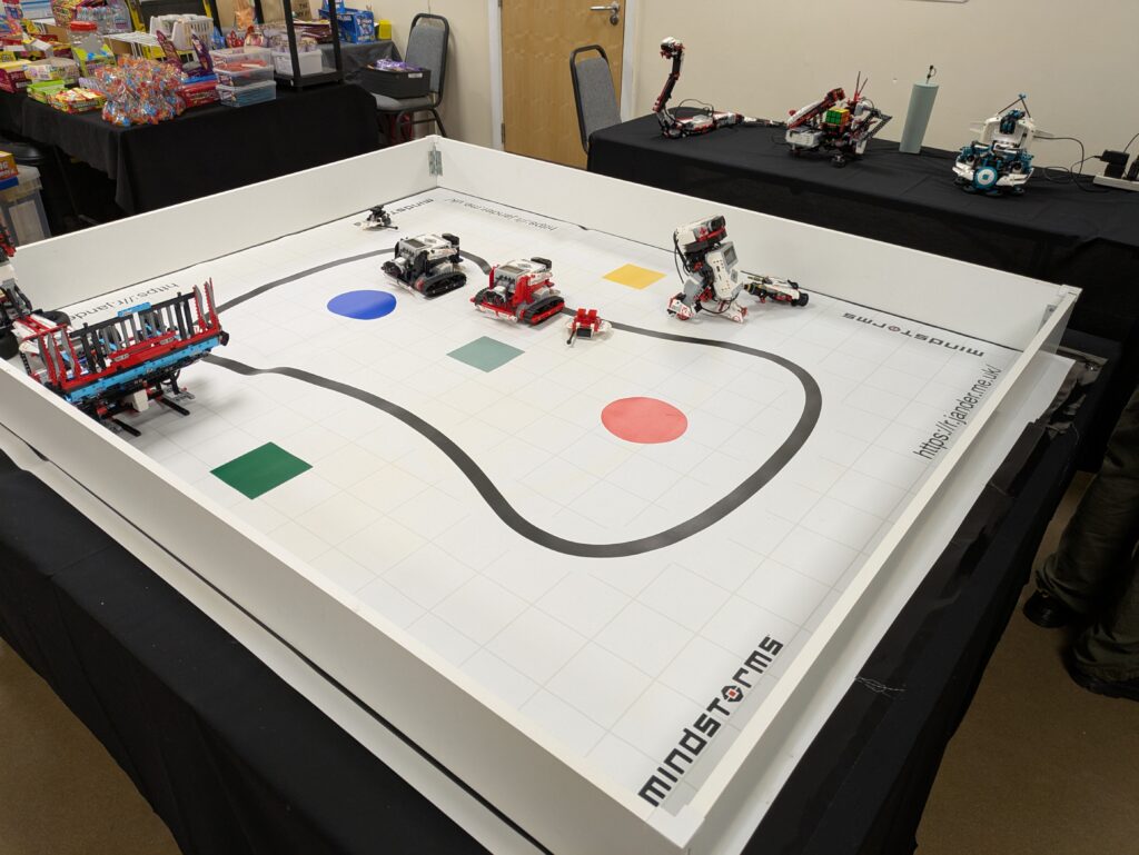
So yesterday was the annual LEGO show over in Mytholmroyd. As usual, a superb but tiring day – I’m not used to 9 hours on my feet 🙂
Surprisingly we went the whole day and didn’t need a single change of batteries, which given that the remote control bots were in non-stop use was rather amazing.
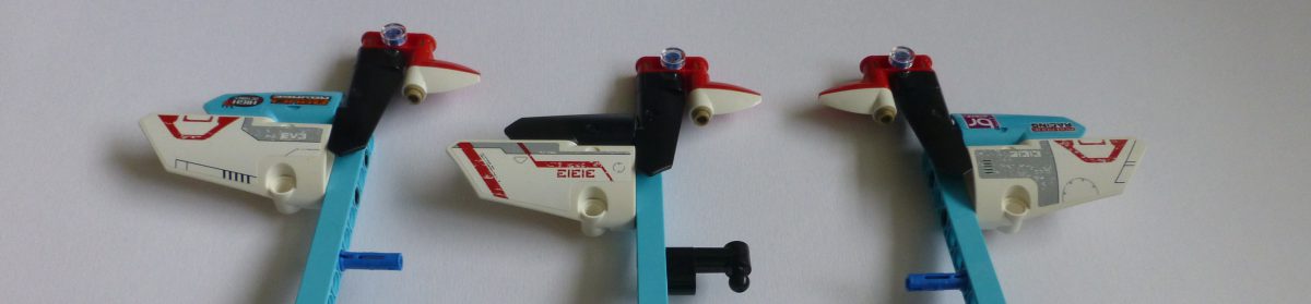
I re-programmed my Bra1der with Pybricks (beta) the week before the show. That proved to be a very good thing. The braider just got on and did its job. No misaligned bobbins going between the slots due to motor overshoots, or weird random slow-downs that the original LEGO firmware used to suffer from. I even tried one of the braids it had been programmed with but I’d never got around to trying. I think it looks rather funky:
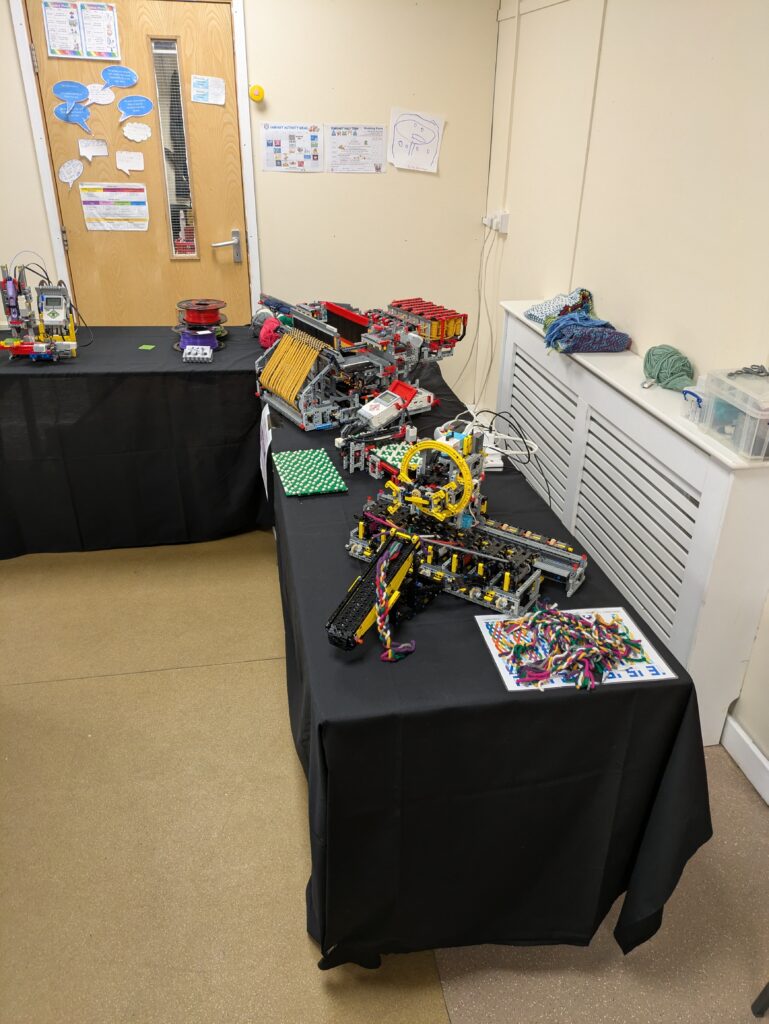
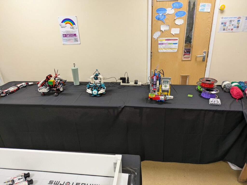
I did have a few issues with some of the bots going a bit potty but nothing insurmountable. The Mindcub3r did go through a period where it wasn’t solving cubes at all – not sure what was going on there. The only thing I can think of is that the EV3 was still set to a 30 minute sleep, so maybe the internal solver was getting killed? Who knows. I did have one casualty. The 3D art pen in the EV3DPrinter blew itself up:
The nozzle got blocked and the filament feed, being at the back, managed to pop the end off. So that was that for the 3D printer for the day. That was a shame as I like having that running. I have done some maintenance on the pen today, so I hope that will be back in operation for the next shows.
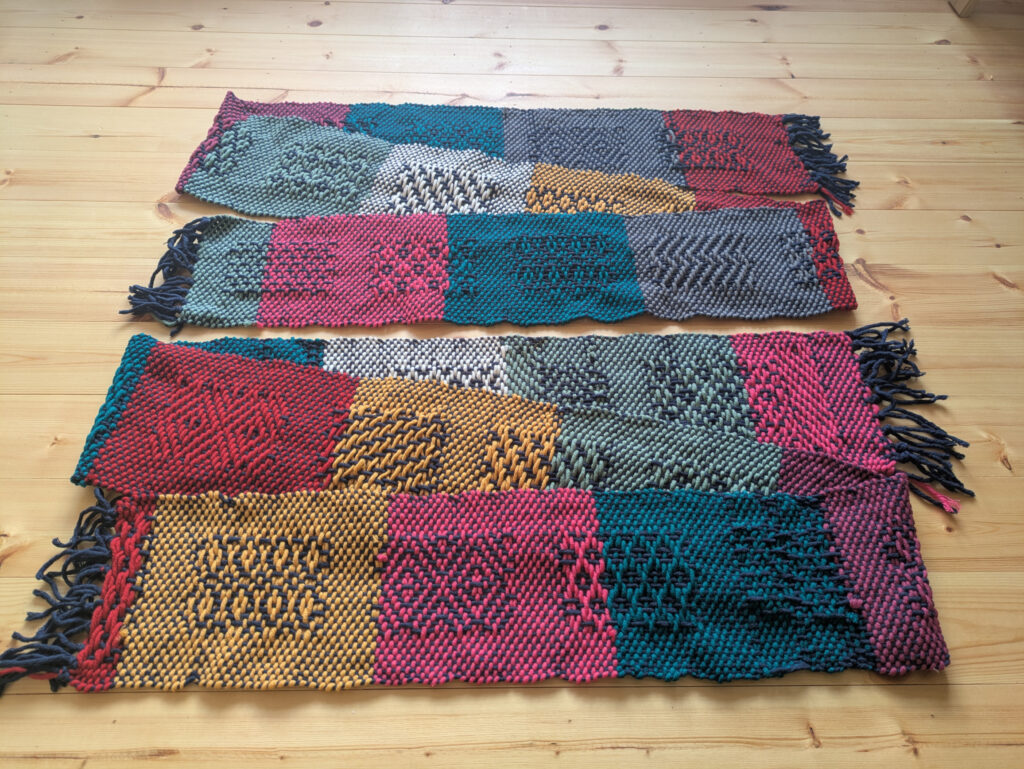
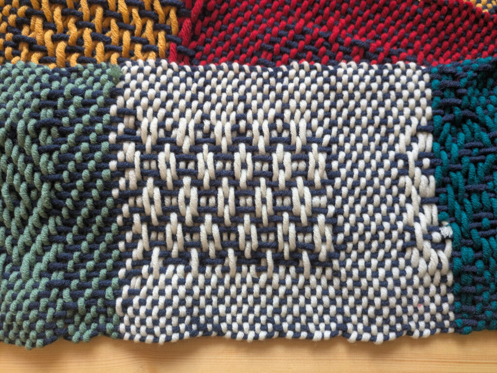
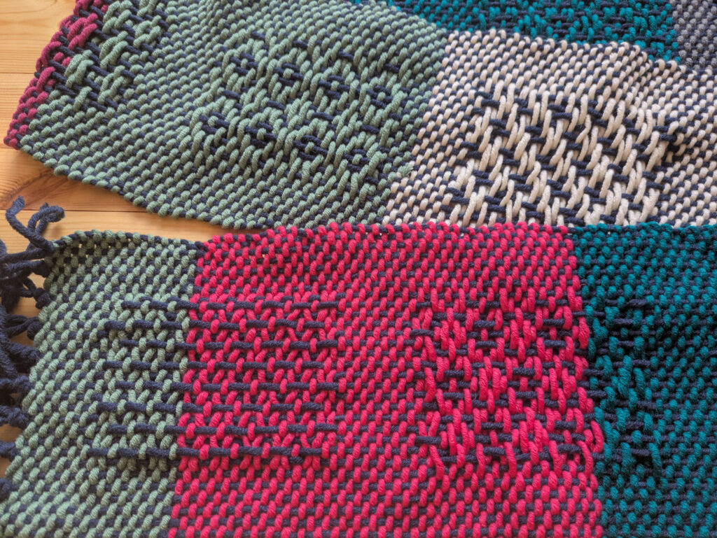
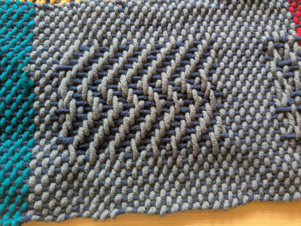
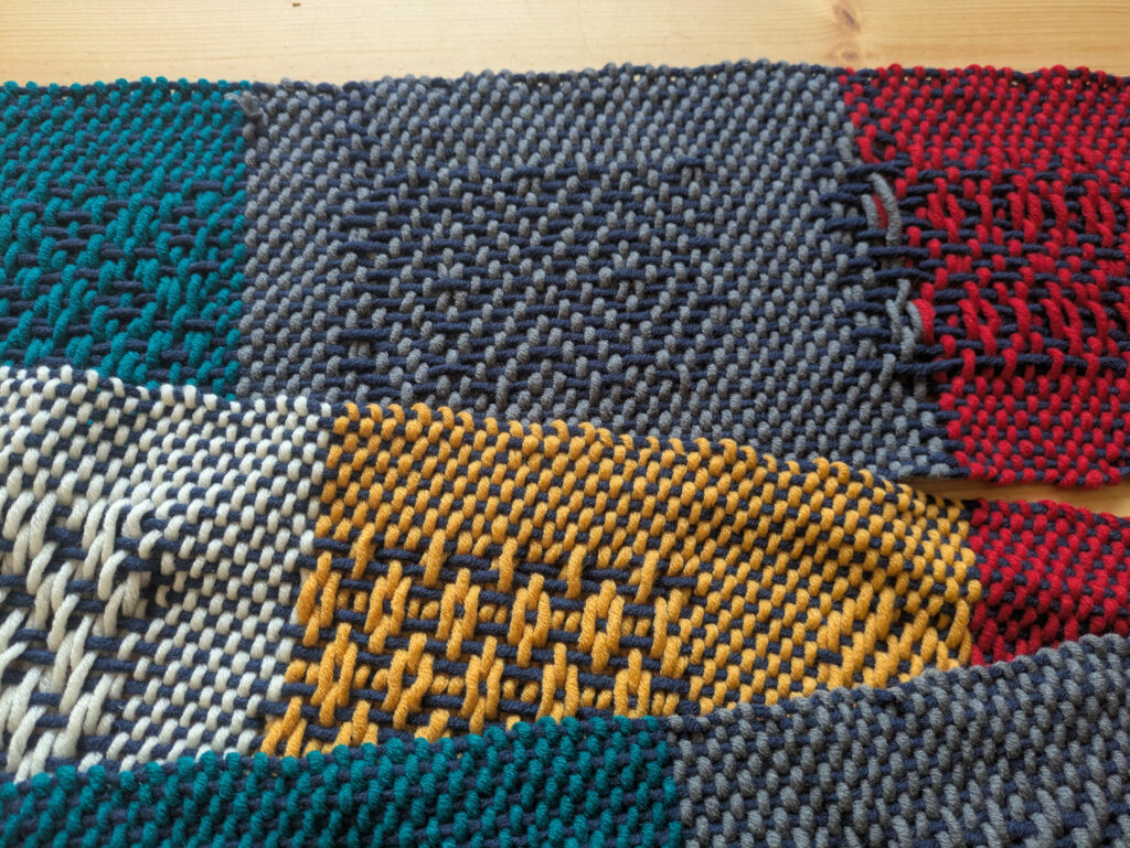
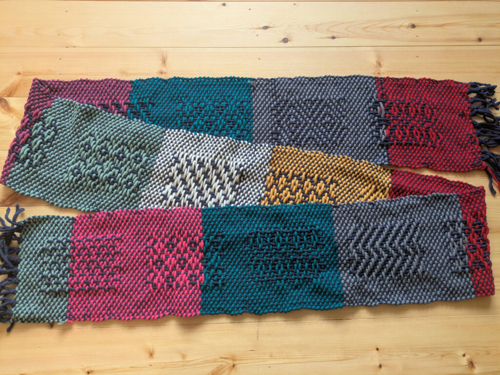
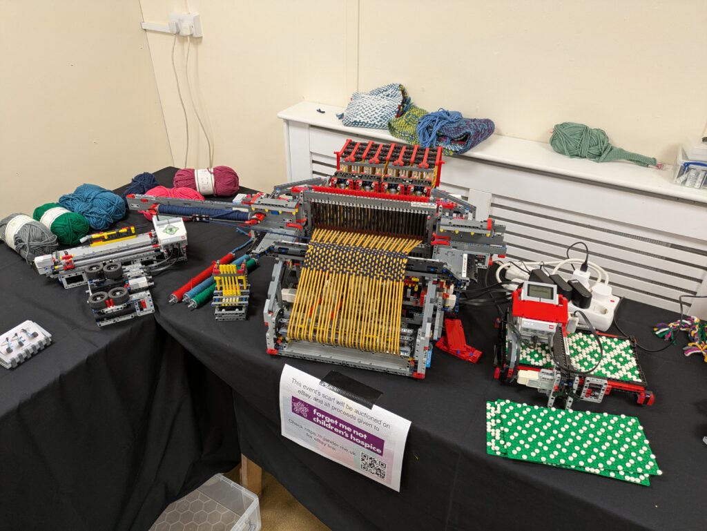
The loom behaved itself perfectly. It probably wove the best scarf it’s ever done! It still had yarn left in the bobbin frame at the end of the day, so I wasn’t able to finish the scarf during the show. I think that’s down to me starting the loom at 11am. I know that a 9am-5pm show will result in a completed scarf.
So, whilst I sit here and type, it’s currently doing a bit more weaving. I’ll finish it off in the next day or so, take some photos, and get it up on eBay with all the proceeds going to the Forget Me Not Children’s Hospice charity. So watch this space for the eBay link!
Several months ago I had been thinking on building a robot that could read the Braille bricks developed by LEGO. They have had them available in a more educational context via their https://legobraillebricks.com/ website for some time now. Unfortunately, these ideas came to nought at that time, so I put the idea to bed.
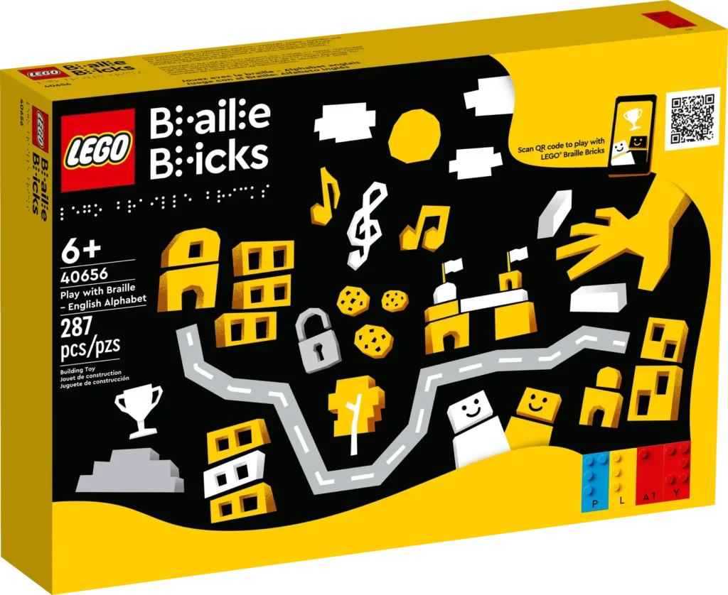
Roll on a few months and the group of RobotMak3rs that I’m a member of had one of their regular remix challenges – i.e. to mix an existing set with some robotics to come up with a new idea. By then the domestic LEGO Braille Bricks set (40656 in the UK) was out, so I figured it was time to revisit my earlier ideas.
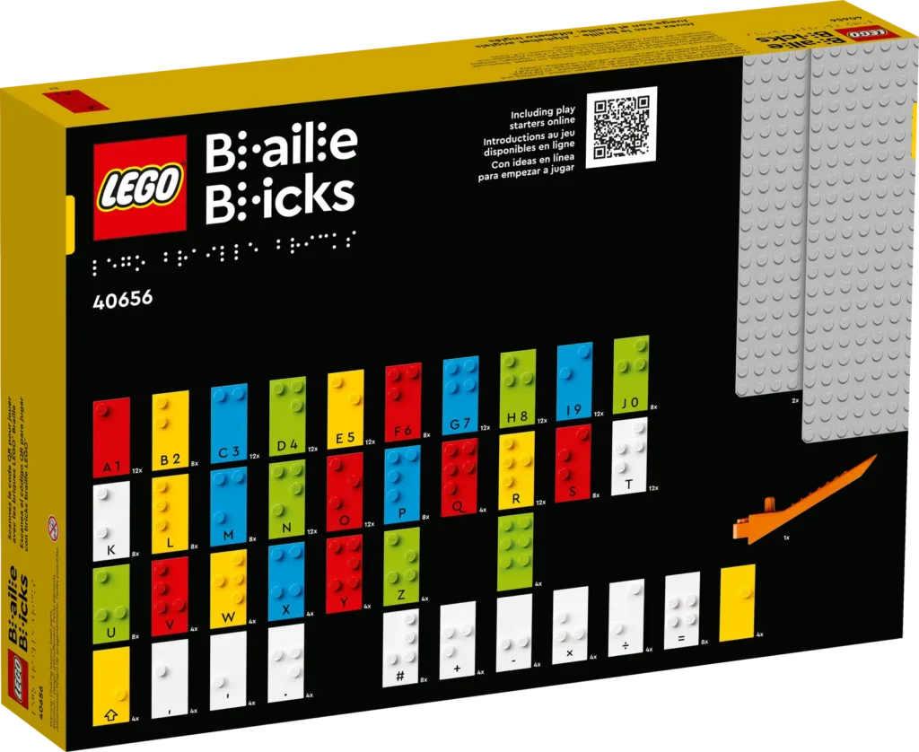
LEGO 40656 FrontLEGO 40656 Back
Initial Ideas
Right at the start I wanted the bot to read out the Braille using text-to-speech (TTS). I wanted to do this as the bricks are intended for visually impaired users so having just display of text would be inappropriate. The Spike/Robot Inventor doesn’t have the ability to generate complex sounds on the hub itself and would have relied on an external app running on a mobile or table to perform that task. Instead I decided it would be far better to use an EV3 running Pybricks micropython as that has the ability to perform TTS output. In addition to wanting the Braille read out, I wanted all the prompts that would appear on screen to have an audio equivalent.
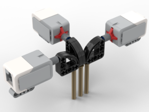
My initial idea for the mechanics was to have three medium EV3 motors each with 3×5 L-beam attached. As the bot moved along the line of Braille it would rotate the motors such that the tip of an L-beam touched either the brick’s stud or the top of the brick. The difference in angle of the motor would indicate a dot or not. However, very quickly this idea was discarded due to the fact that the stud height is only 1.7mm. The height, and therefore angle change was not sufficient to accurately distinguish the presence of a stud or not. Also this would have required three motors, only allowing one remaining to move the bot along a row. Since I wanted to have it be able to read multiple rows of text, I’d have needed 5 motors (X, Y, +3 for touch) which is not possible with an EV3. So I discarded this approach.
My next idea was for a bot that had an arm with three touch switches mounted on it and have the arm lift up and down. This way the angle of the motor would be irrelevant. The arm would need to move up and down on to each column of studs so that it wouldn’t get snagged on the next column as it moved sideways.
I went through various arrangements of the switches, settling on something similar to below for a number of prototypes:
The principle here was that the stud would push against the pin, which in turn via rotation of the 3×3 quarter circle beam would press in the button. The motors would have had to be mounted at 90° to each other due to the width of the switches (initially) preventing them being next to each other. The big problem with all of these designs is that the springs in the switches are remarkably firm. The motor, pushing the arm down, would have to apply a significant force – akin to trying to hold out a 1kg mass at arms length. Also, it looked ugly. I tend to work on the principle that if it’s ugly then it’s likely to be wrong.
The ‘Fingertip’
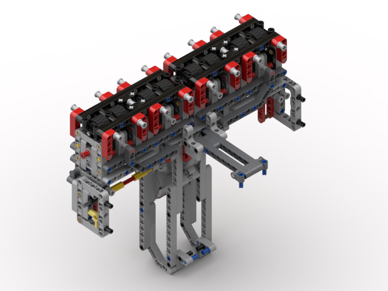
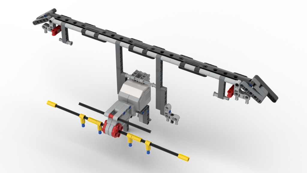
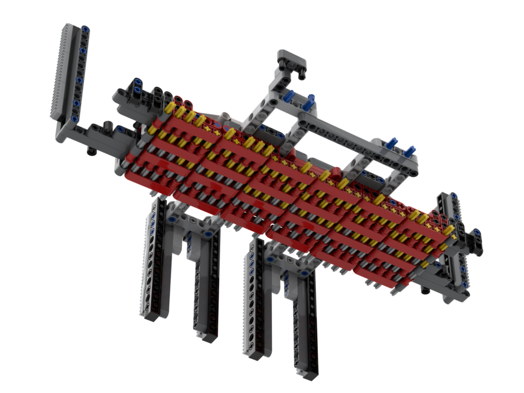
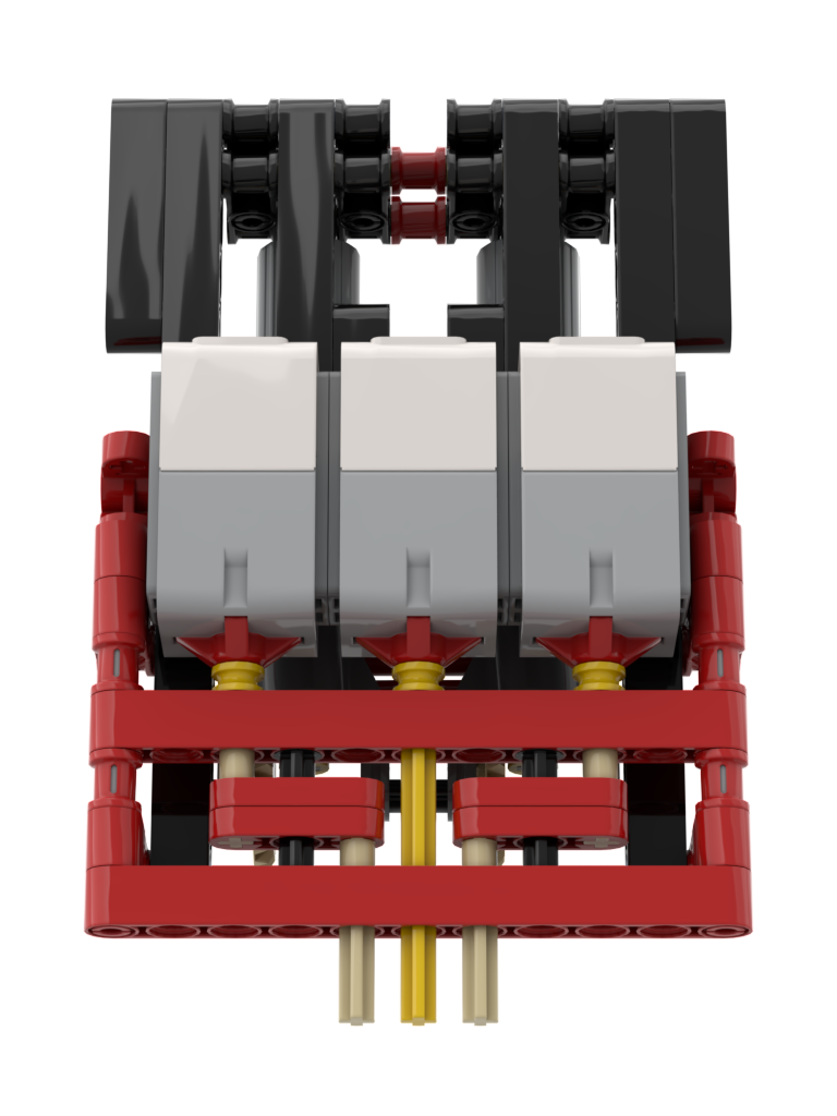
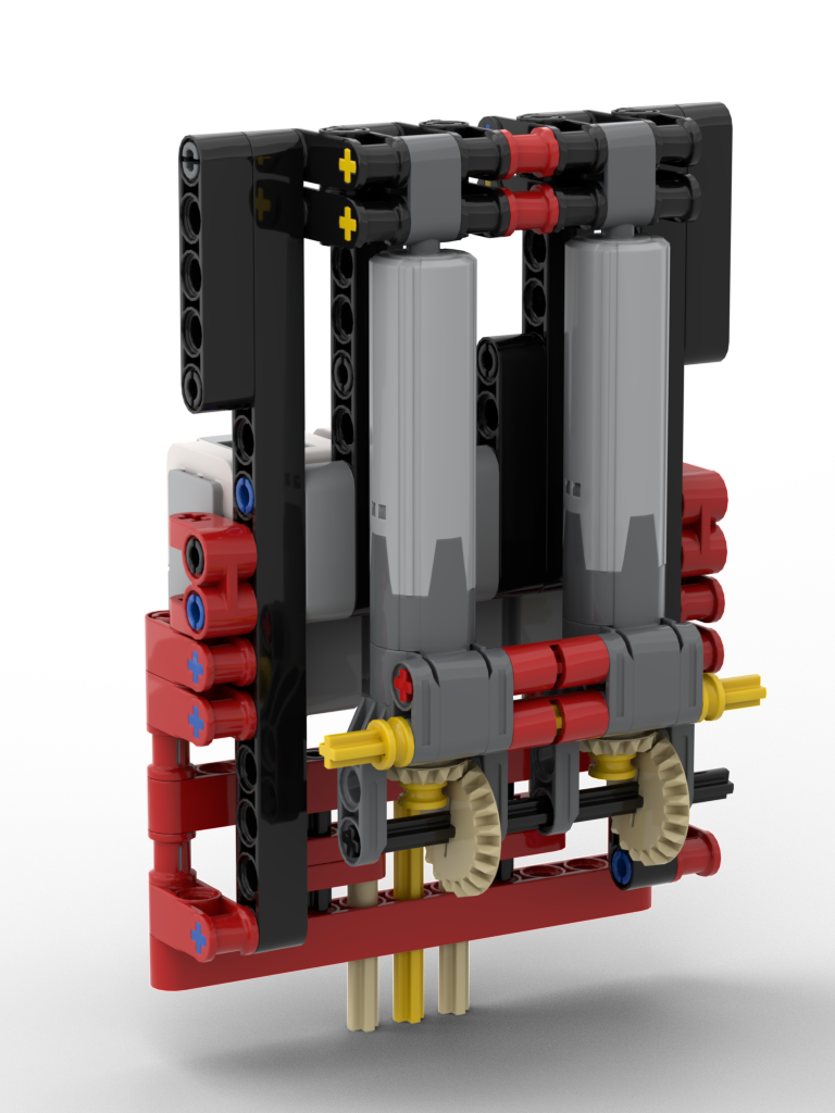
After going through several iterations of the ideas above, I had a brainwave. It was possible to mount the motors in parallel and ‘dog-leg’ the pins such that they could also touch the studs. To counter the issue of the required force to press in the switches, linear actuators would be used instead. Although this would slow down the sensing action it would trade speed against accuracy. I ended up with the mechanism below:
Dog-Legged PinsLinear Actuators
This mechanism worked perfectly, with an unexpected discovery on the switches, discussed further on.
Bridge, Switches, and Calibration
The Braille sensing mechanism (the ‘lift’ as I think of it) needed to move in both X axis and Y axis, so that the several rows of bricks could be placed on the baseboards supplied with the kit. The lift would be mounted on a bridge, allowing for Y-axis movement, and the bridge itself would move in the X-axis. The bridge took a few attempts to get right. Due to a combination of the mass of the lift and the force required to press in the switches resulted in flexing of the bridge, so this required a few revisions to get it rigid enough but not too bulky
One thing I had never realised about the EV3’s switches is that they trigger at the start of their travel, i.e. they don’t need to be pushed all the way in to trigger. Had they needed to be depressed all the way, it’s quite possible this model would never have worked. Due to LEGO being plastic, the parts are never perfectly aligned. This could have meant that one of the switches may have reached the end of its travel before either/both of the other switches had triggered. No amount of extra downward force could have pressed the other two as this switch would have blocked any more movement. Thankfully they trigger at the start, so it’s still possible to push down, thus enabling the neighbouring switches to also trigger.
Due to slight flex in the model, it’s not possible to have the motor wind the linear actuators to the same place per row of Braille. The middle two rows can require a little more force. To solve this the bot requires calibration on first use, and offers to calibrate on start up as well. Calibration requires that an L (⠇) brick is placed at the start of each row, then the bot tests each of those bricks. For each row the motor position for the last switch to activate is stored on disk, for repeat use, then when in use it drives the motor to just beyond the motor angle to ensure that all switches could be activated.
Accessibility
As I said at the start, I wanted this model to be accessible to the target users, so all instructions are read out as well as displayed on screen. All button operations have a small click to provide audio feedback, along with a relevant audio prompt, e.g. saying which row has been selected to read. To aid in placing the Braille bricks on the baseboard there are tiles on the first column. Subsequent bricks are simply placed next to the previous bricks. The EV3 has been oriented so that the speaker is facing the user so that it can be heard.
Video
As part of our group’s remix challenge we have to produce a video relating to our build. I opted to have the video show parts of the robot and it in operation. Since the bot converts the Braille to speech, I figured I’d have the voice-over performed by the bot as well (I’m never a fan of speaking on camera, and being a Brit I always feel that I sound sarcastic 😆). I also thought that it would be a fun little feature to have the subtitles show in Braille first and the wipe over to the actual text. The resulting video is below:
On first ever run of the program, it will pre-generate all the pre-coded speech prompts. This is so that the program doesn’t have to perform the TTS step every time a common speech prompt is needed. It will only do this the once.
On first run of the program it will insist on a calibration step. It will offer to perform a calibration on every other run, but it defaults to ‘no’. To calibrate perform the following:
Put an L brick at the start of each of the 4 rows
Press the centre button. This will then test each of the sensors and motor and store for future use
Lay out the Braille as wanted. There are 4 rows that can be used. Select the row to be read with the left and right buttons, centre to read. Spaces between words can be either one or two columns of studs wide. Three or more empty columns will end the row of text.
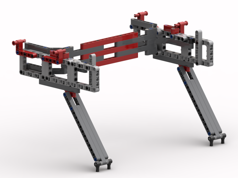
In March 2021 the members of the RobotMak3rs RLOC were challenged to come up with ideas for an Olympic Games remix involving two kits, one robotic and one non-robotic. My idea was to mix the LEGO White House (21054) kit:
The model has two modes of operation: automaton and game. In automaton mode, the horse will go around the arena leaping over the jumps of its own accord. In game mode, there are speed and jump controls and the player attempts to get the horse’s speed right and jump at the correct time. A video showing the model in operation and some of the details about it is below:
Model Operation
What was not shown in the video is how to start the model off. The model needs to set its initial positions. It does this by rotating the jump motor to its 0° position, then repeatedly rotating the horse motor to its 0° position until the horse ends up in its start position. This is required due to the 36T:60T gearing used to drive the horse’s position. The colour sensor will detect the white 3L beam when it’s in the start position.
The steps to start the model off are:
Before starting the code, remove all the jumps – so that they don’t get knocked over during initialising.
Start the program. The horse will go through its location detection steps.
Replace all the jumps back to their positions
Tap the hub – it waits for a tap gesture before carrying on
Enjoy the model’s action.
Build Instructions and Code
I have produced build instructions which are linked to below. There are two programs, one for each mode that are also available below. The code has been written in the default block language for the 51515 hub. My BIs and code are released under the Creative Commons Attribution-NonCommercial-ShareAlike 4.0 International licence:
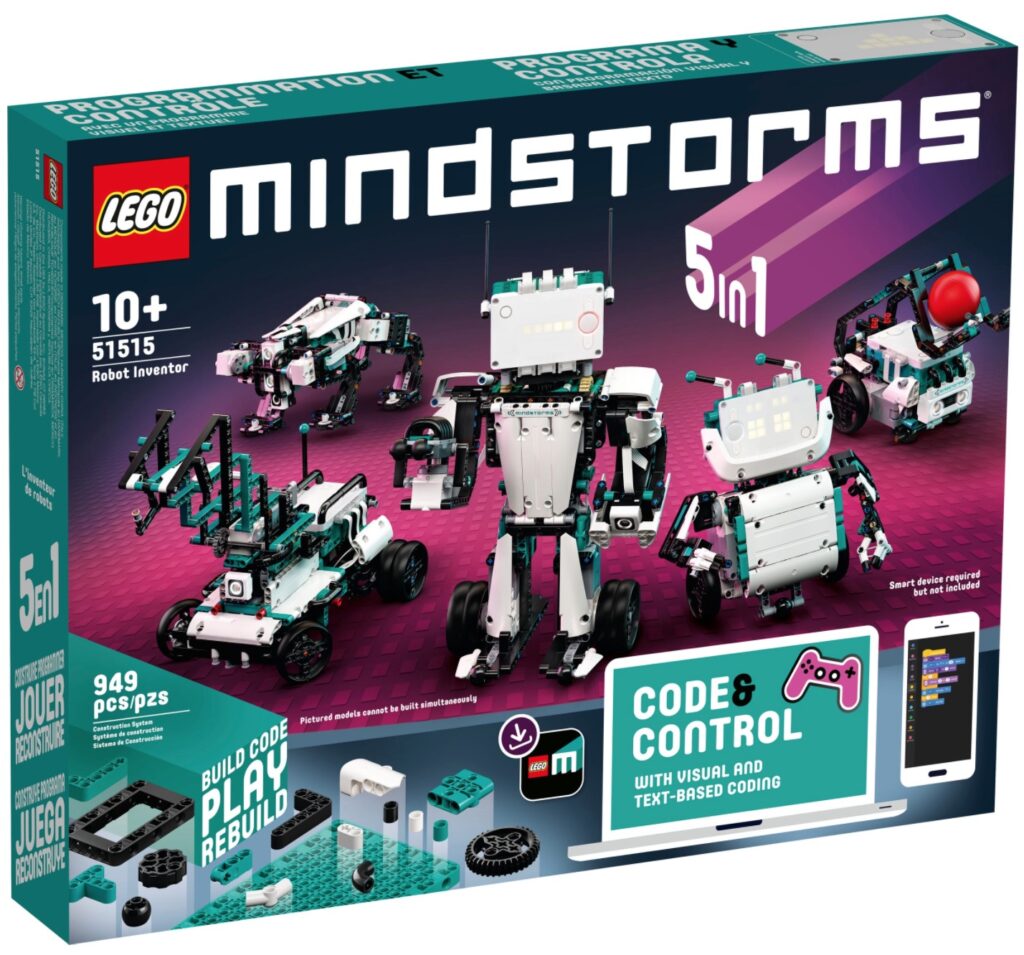
Over the past week or so, several members (including me) of the RobotMak3rs RLOC have been having a lot of fun playing with LEGO’s new Robot Inventor kit (51515), which will be released on 15th October this year. Many thanks goes to LEGO and the RobotMak3rs RLOC for supporting our ideas.
My idea was for us, as world-wide community, to have fun building some of the models together. Here’s the first of the videos – Charlie: