Why did it take me so long?
Well. The loom is a very complex model and a lot of it was built on-the-fly as it were. I kept changing things on the original design, back in 2016 (!), until it worked – well, worked enough. A lot of that, understandably, was right on the inside of the model. To make BIs (build instructions) of that would require taking it apart – which was a very scary thought. So, I basically avoided doing that for as long as possible. Since the loom worked, I didn’t want to risk it not working again after being taken apart.
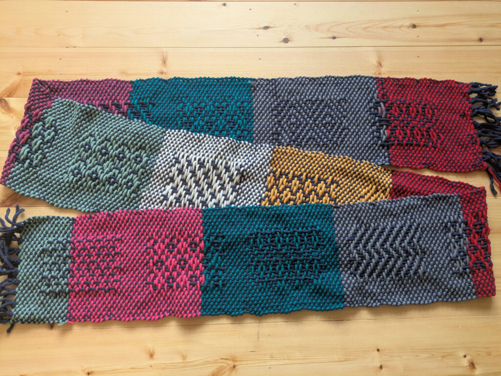
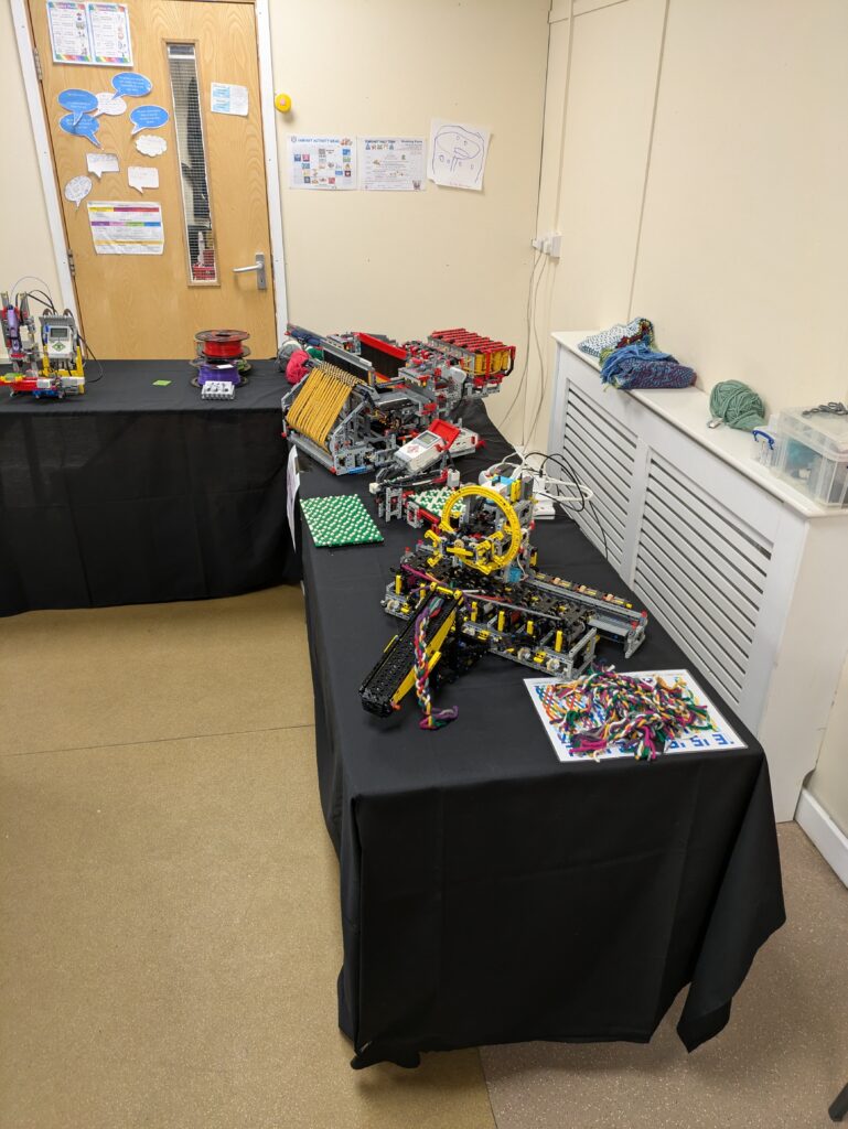
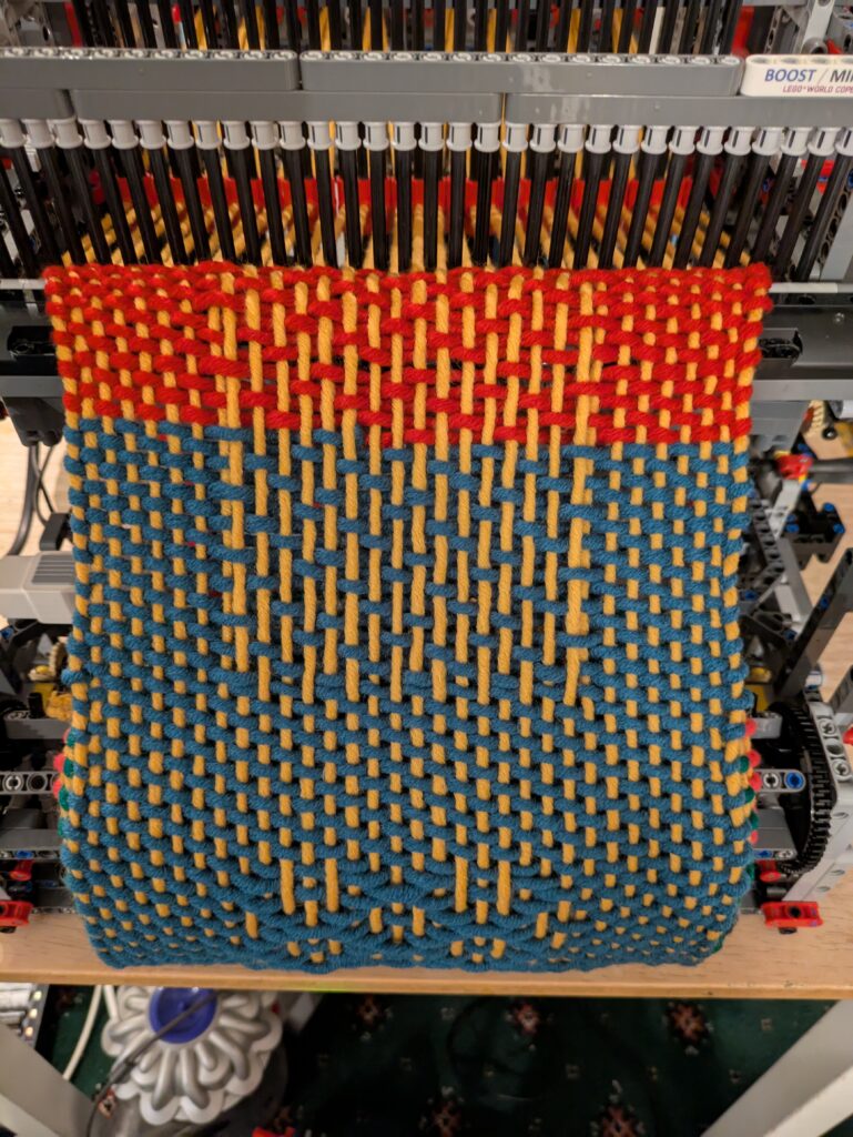
I showed the loom off at Brickstastic ’26 this year. Unfortunately, on the first day, one of the large motors died. You can of course guess whereabouts the motor was. Yup, right inside. It was the heddle lift motor which, to be fair about it, has the hardest job and had done a lot of scarves in its time. It took me about 15 minutes, kneeling on the floor, to extract the dead motor and to swap in a spare – which I had fortunately decided to take with me. Over the past 2 years I’ve had 4 large motors fail on me in various robots, so I was concerned that another might fail.
Given that I’d had this failure, I was concerned about the other motors. So I figured it was time to bite that metaphorical bullet and give the loom a good clean, swap out any stiff motors with my spares, and take the opportunity to make the BIs.
A quick aside about motors
Thankfully I had a few spare motors in. Initially destined for a possible knitting machine which, according to my current thoughts, will need 15 motors! Having had 3 motors fail, before this one, I’ve been investigating options for repairing them. The large motors are actually relatively easy to take apart. The brass gear on the motor does need a blow torch, a catering one works, to remove as it’s an interference fit. The issue I’ve found is getting new DC motors with the correct speed. That hunt has failed me so far. I did succumb to buying some clones from AliExpress and, apart from cheaper feeling plastic, they do appear to be good alternatives. The speed is correct and they’re a little quieter than official ones.
Back to Build Instructions
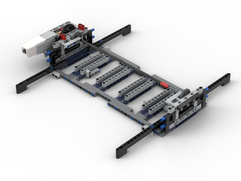
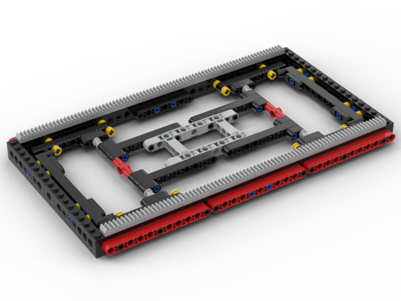
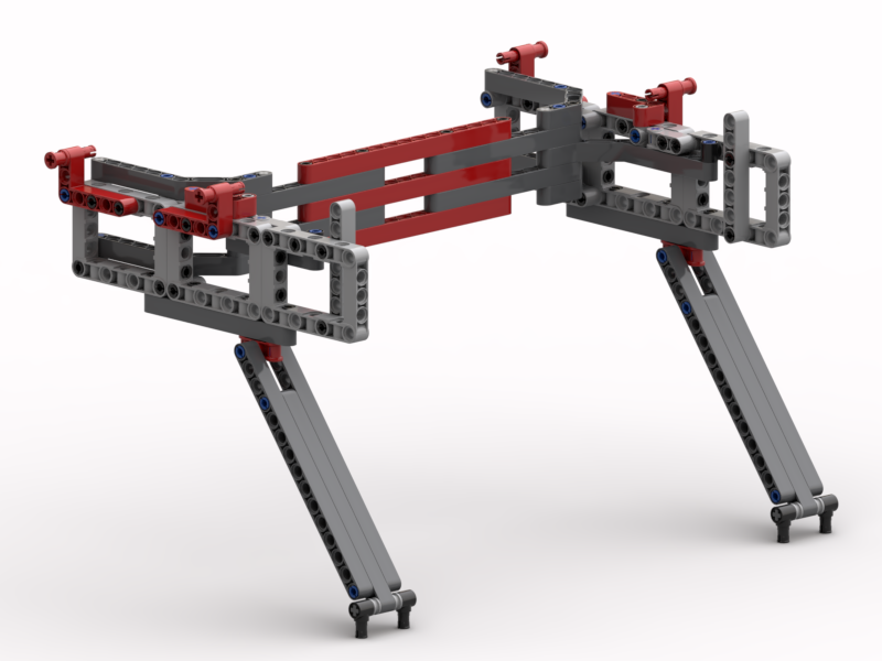
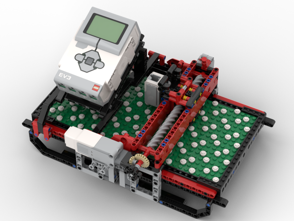
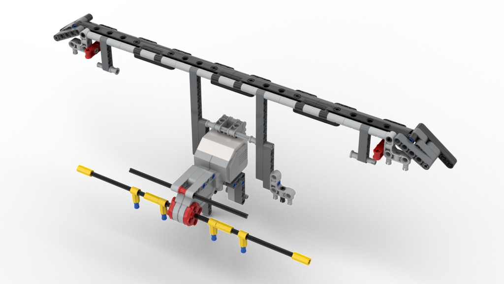
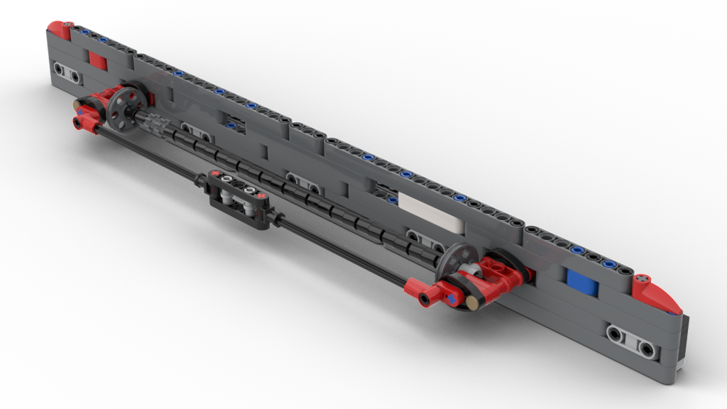
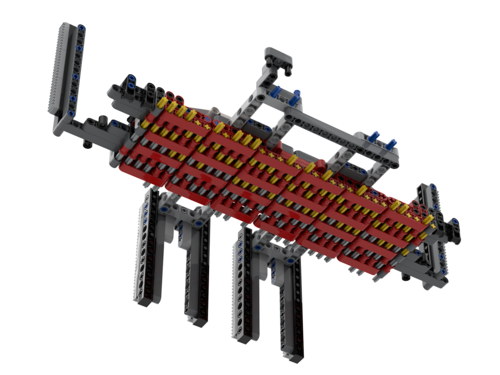
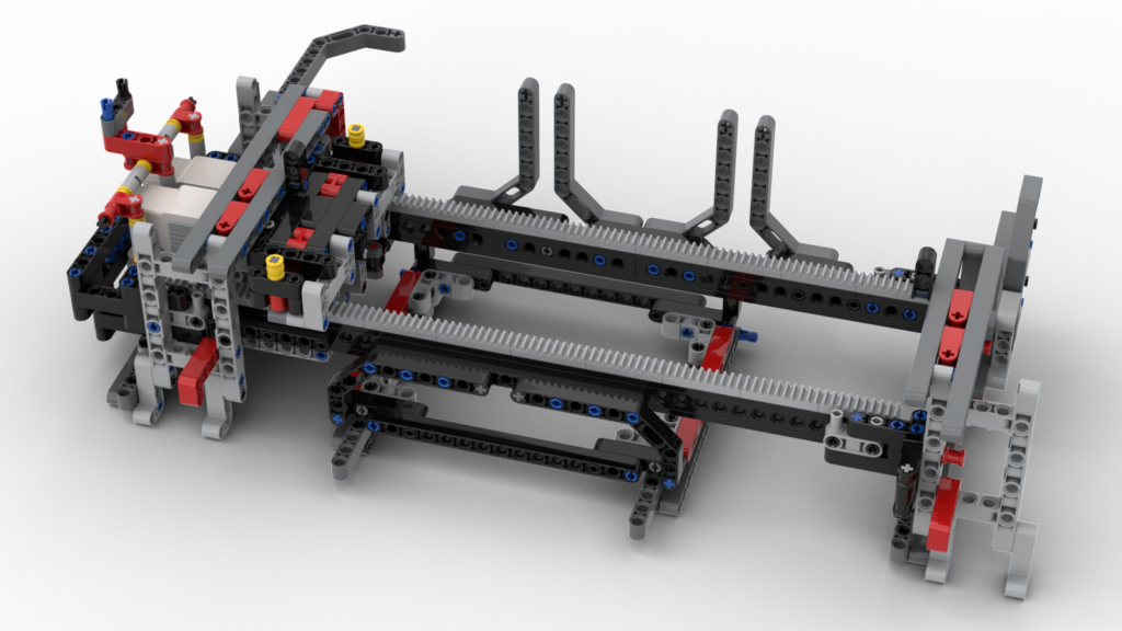
Over the years I had already made models for parts that I had either replaced or added, e.g.
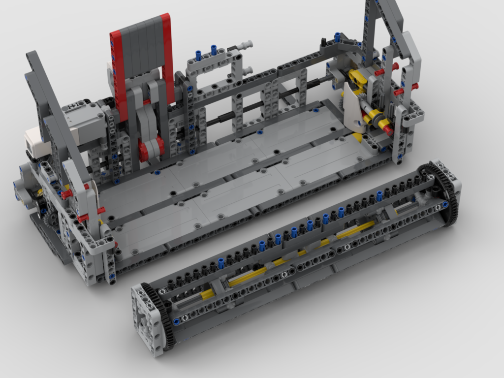
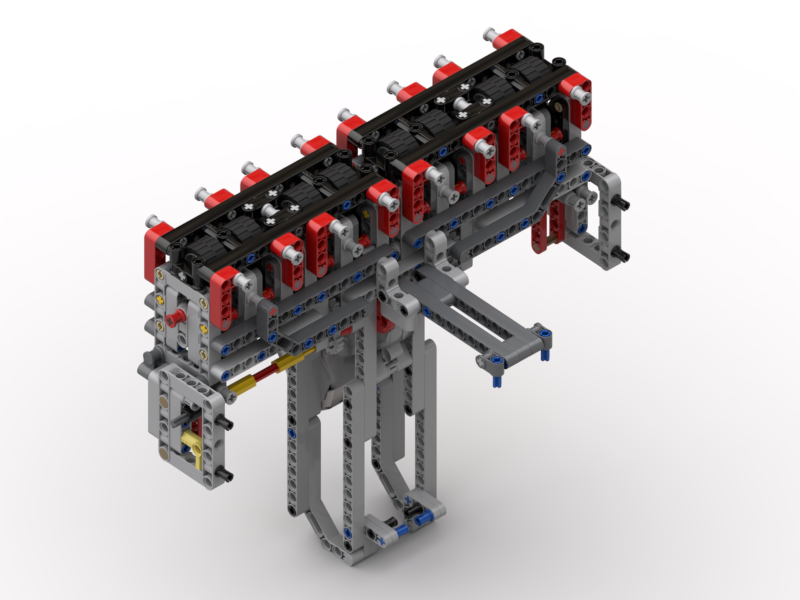
Making the rest of the model has been a labour of love. It’s taken me a couple of weeks of working out how I can pull sections of the loom, and then modelling them.
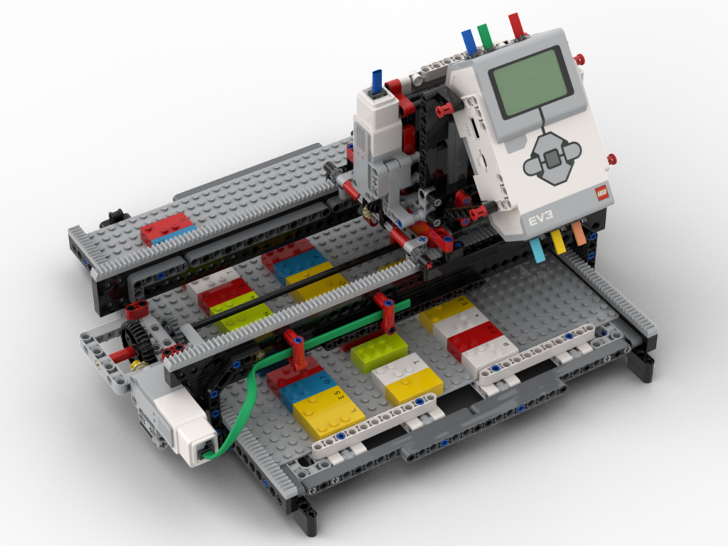
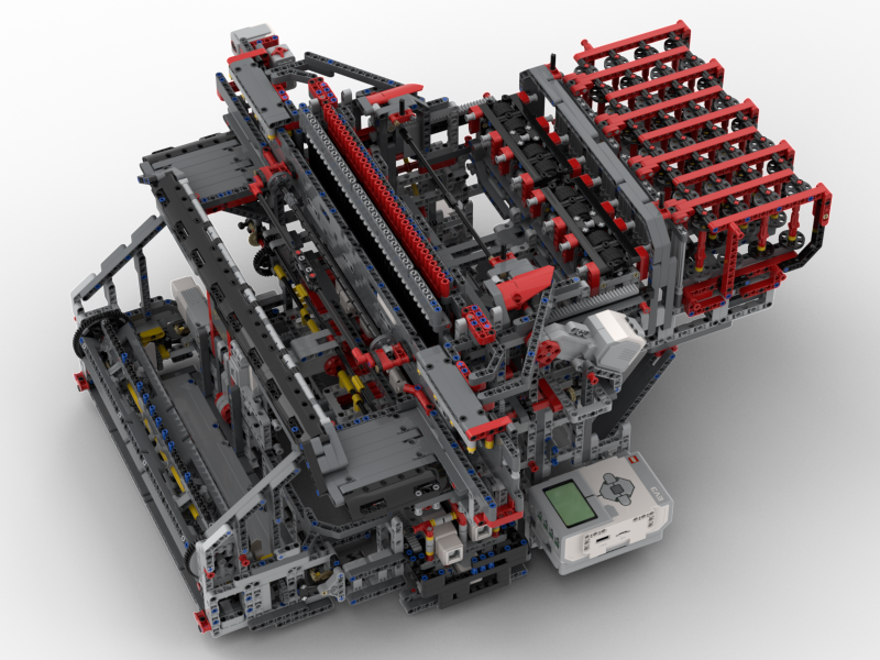
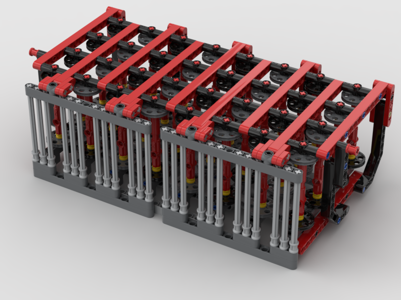
What has amazed me is how many parts are in this loom. I’d always thought it was a couple of thousand or so. I was so wrong. There are 5,659 parts in the body of the loom alone! There are a further 590 parts in the scanner. What then amazed me more is that 40% of the part count is connecting pins, 2291 one of them.
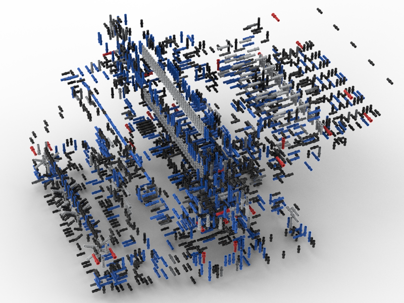
For fun, I have also rendered the above as a rotating animation:
The Bad News
Sorry folks. After putting all this effort in to making the BIs, I’ve decided that they’re currently just for my benefit. I like the fact that this is a unique model and that there is only one of it in the world. The BIs are rather complex and I made the decision that some sub-sections would actually require a bit of dismantling to get into place as it made the modelling easier for me. The other issue is that the loom is programmed in EV3g, which will be hard for many to find the application for.
What I may consider is releasing a “single step” LDraw file with all the parts in the right places so others can at least look at it as a model. I’ve not yet decided on that.
The Future
Now that Pybricks supports the EV3, I am planning on re-writing the whole system using that. I can’t really start on that until Pybricks supports Bluetooth as there are 3 EV3s in the model that communicate that way.
Maybe, when it is in Python, I might re-consider my thoughts on sharing the BIs. I’m still not sure on that though.