Several months ago I had been thinking on building a robot that could read the Braille bricks developed by LEGO. They have had them available in a more educational context via their https://legobraillebricks.com/ website for some time now. Unfortunately, these ideas came to nought at that time, so I put the idea to bed.
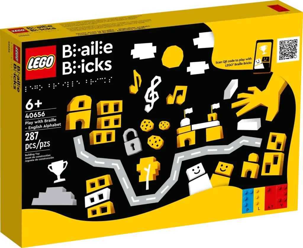
Roll on a few months and the group of RobotMak3rs that I’m a member of had one of their regular remix challenges – i.e. to mix an existing set with some robotics to come up with a new idea. By then the domestic LEGO Braille Bricks set (40656 in the UK) was out, so I figured it was time to revisit my earlier ideas.
Initial Ideas
Right at the start I wanted the bot to read out the Braille using text-to-speech (TTS). I wanted to do this as the bricks are intended for visually impaired users so having just display of text would be inappropriate. The Spike/Robot Inventor doesn’t have the ability to generate complex sounds on the hub itself and would have relied on an external app running on a mobile or table to perform that task. Instead I decided it would be far better to use an EV3 running Pybricks micropython as that has the ability to perform TTS output. In addition to wanting the Braille read out, I wanted all the prompts that would appear on screen to have an audio equivalent.
My initial idea for the mechanics was to have three medium EV3 motors each with 3×5 L-beam attached. As the bot moved along the line of Braille it would rotate the motors such that the tip of an L-beam touched either the brick’s stud or the top of the brick. The difference in angle of the motor would indicate a dot or not. However, very quickly this idea was discarded due to the fact that the stud height is only 1.7mm. The height, and therefore angle change was not sufficient to accurately distinguish the presence of a stud or not. Also this would have required three motors, only allowing one remaining to move the bot along a row. Since I wanted to have it be able to read multiple rows of text, I’d have needed 5 motors (X, Y, +3 for touch) which is not possible with an EV3. So I discarded this approach.
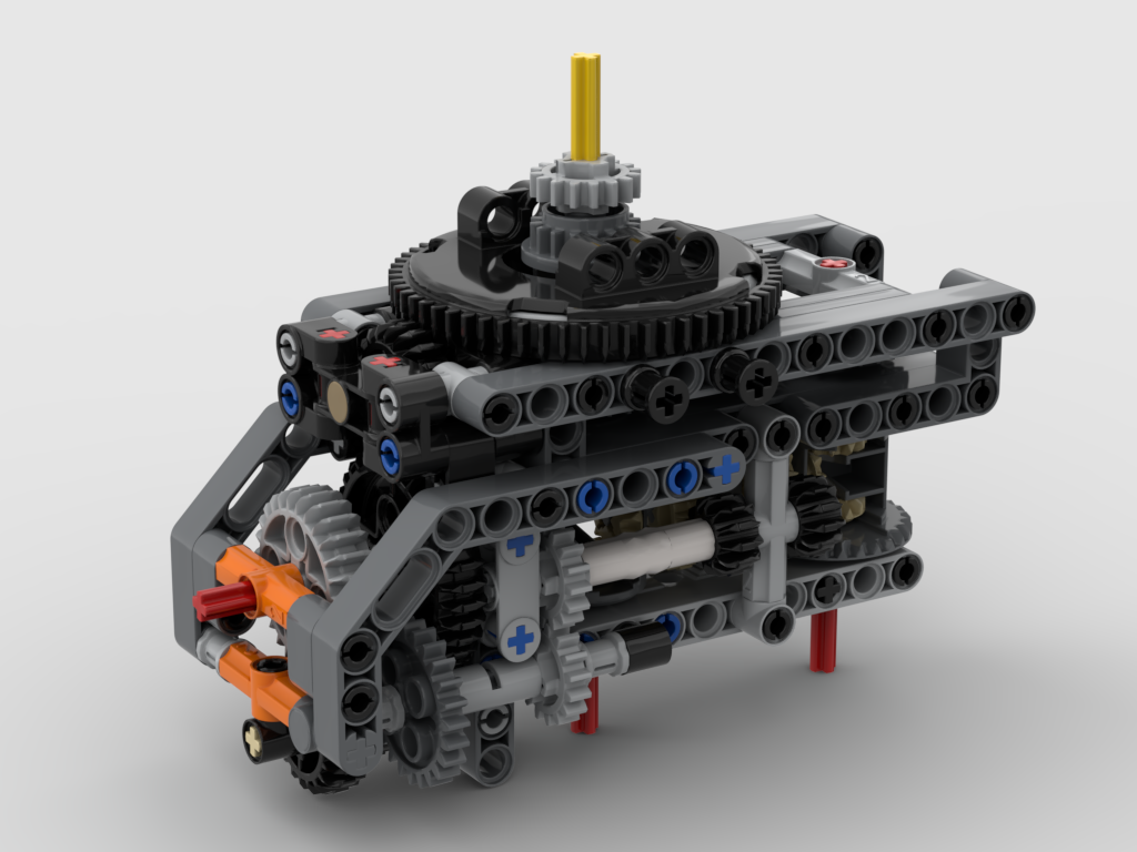
My next idea was for a bot that had an arm with three touch switches mounted on it and have the arm lift up and down. This way the angle of the motor would be irrelevant. The arm would need to move up and down on to each column of studs so that it wouldn’t get snagged on the next column as it moved sideways.
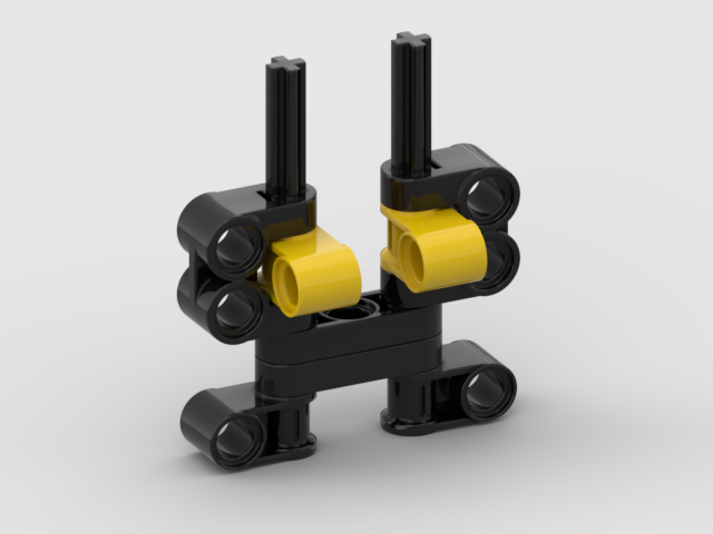
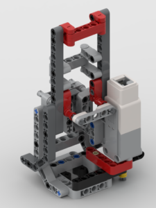
I went through various arrangements of the switches, settling on something similar to below for a number of prototypes:
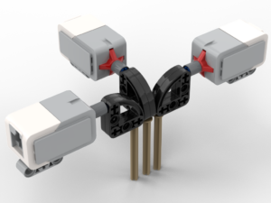
The principle here was that the stud would push against the pin, which in turn via rotation of the 3×3 quarter circle beam would press in the button. The motors would have had to be mounted at 90° to each other due to the width of the switches (initially) preventing them being next to each other. The big problem with all of these designs is that the springs in the switches are remarkably firm. The motor, pushing the arm down, would have to apply a significant force – akin to trying to hold out a 1kg mass at arms length. Also, it looked ugly. I tend to work on the principle that if it’s ugly then it’s likely to be wrong.
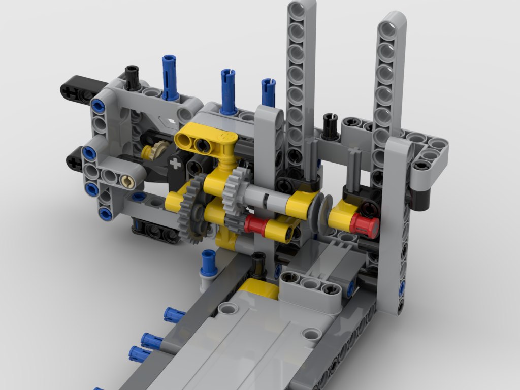
The ‘Fingertip’
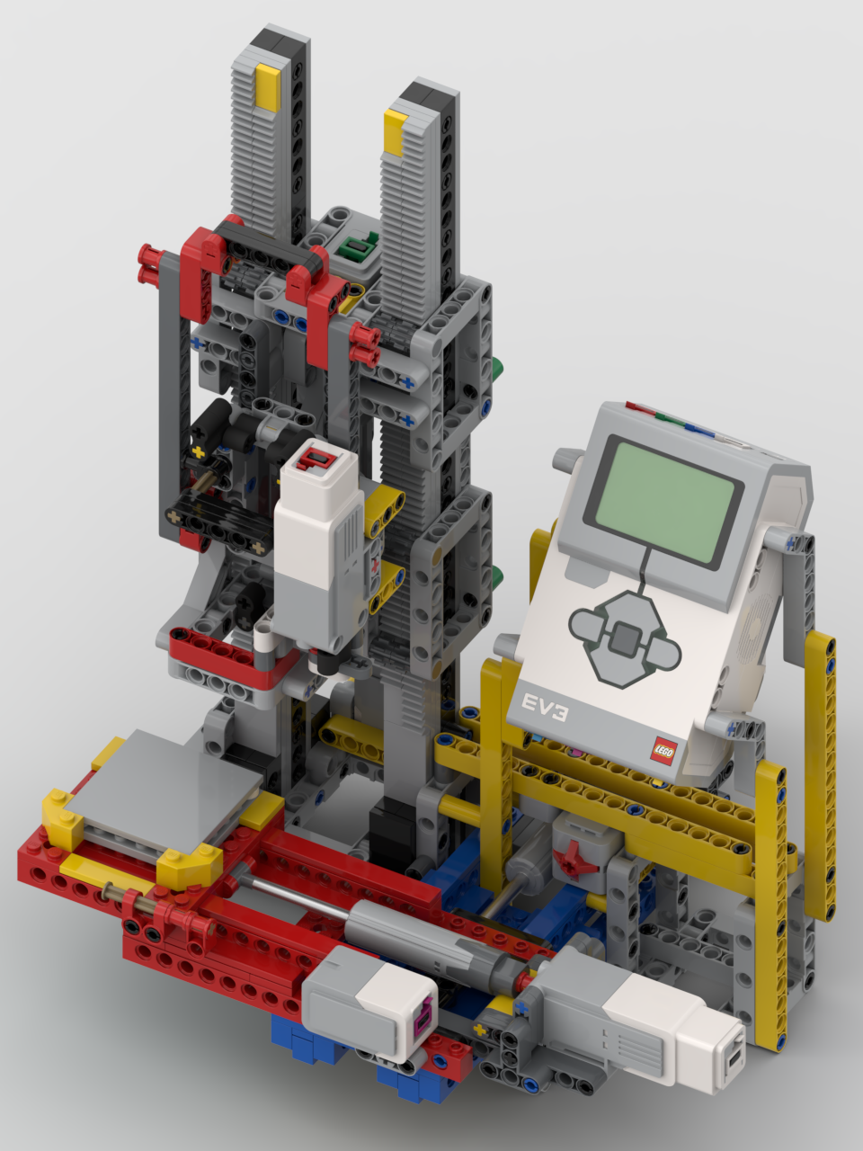
After going through several iterations of the ideas above, I had a brainwave. It was possible to mount the motors in parallel and ‘dog-leg’ the pins such that they could also touch the studs. To counter the issue of the required force to press in the switches, linear actuators would be used instead. Although this would slow down the sensing action it would trade speed against accuracy. I ended up with the mechanism below:
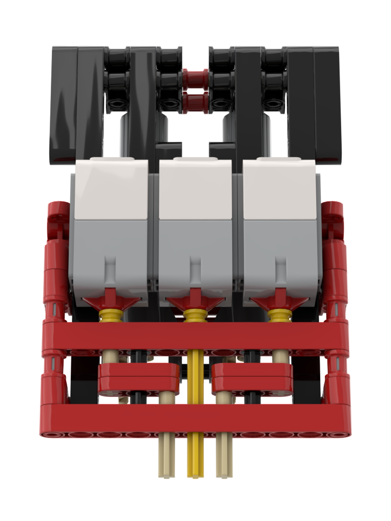
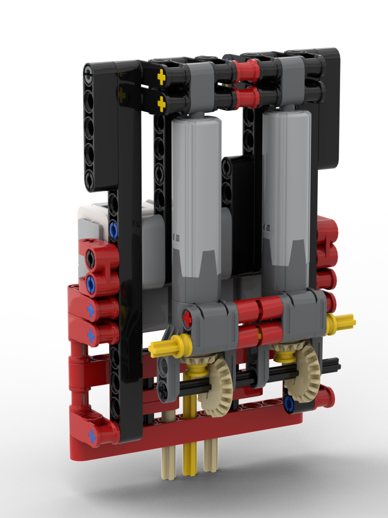
This mechanism worked perfectly, with an unexpected discovery on the switches, discussed further on.
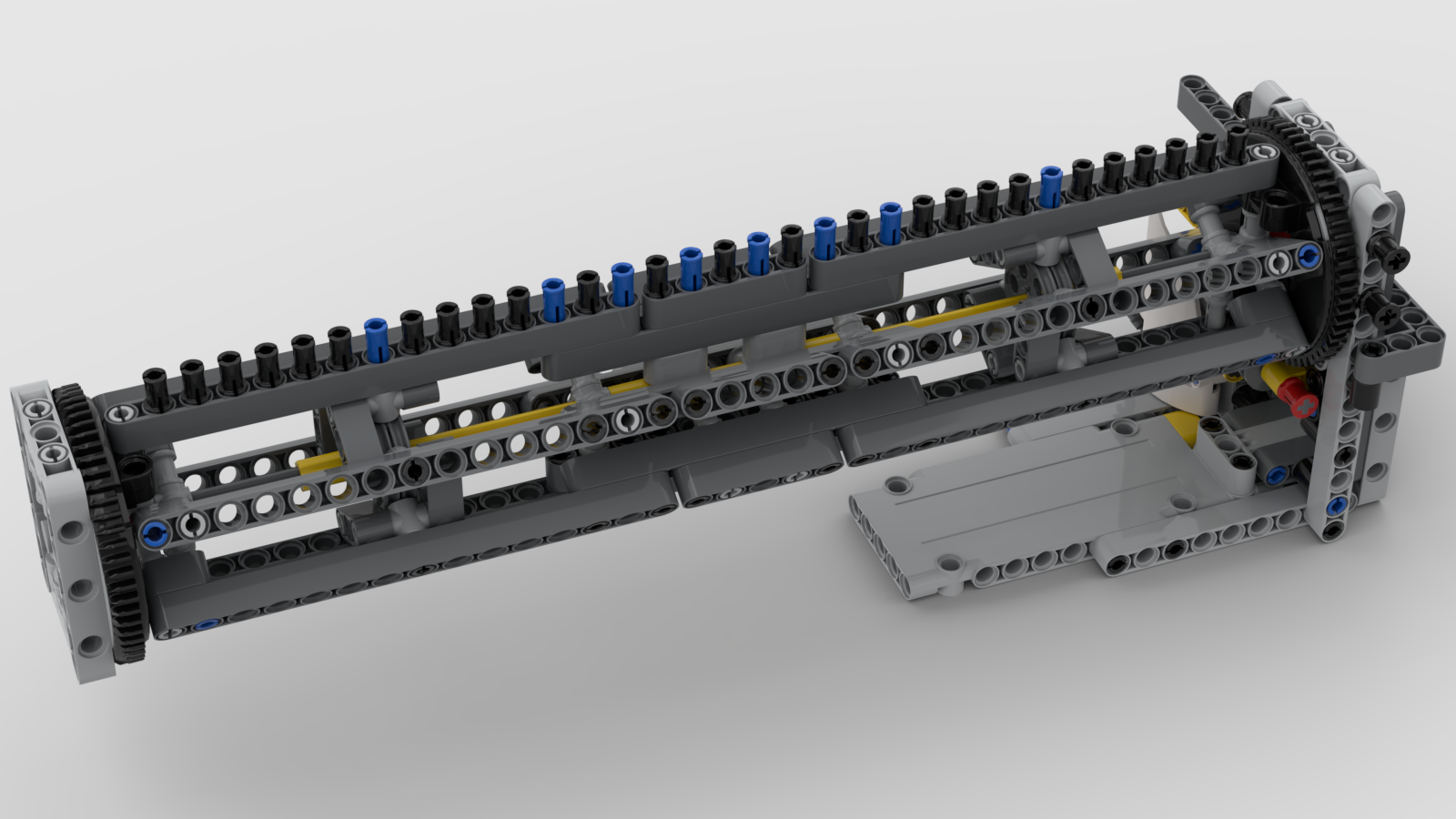
Bridge, Switches, and Calibration
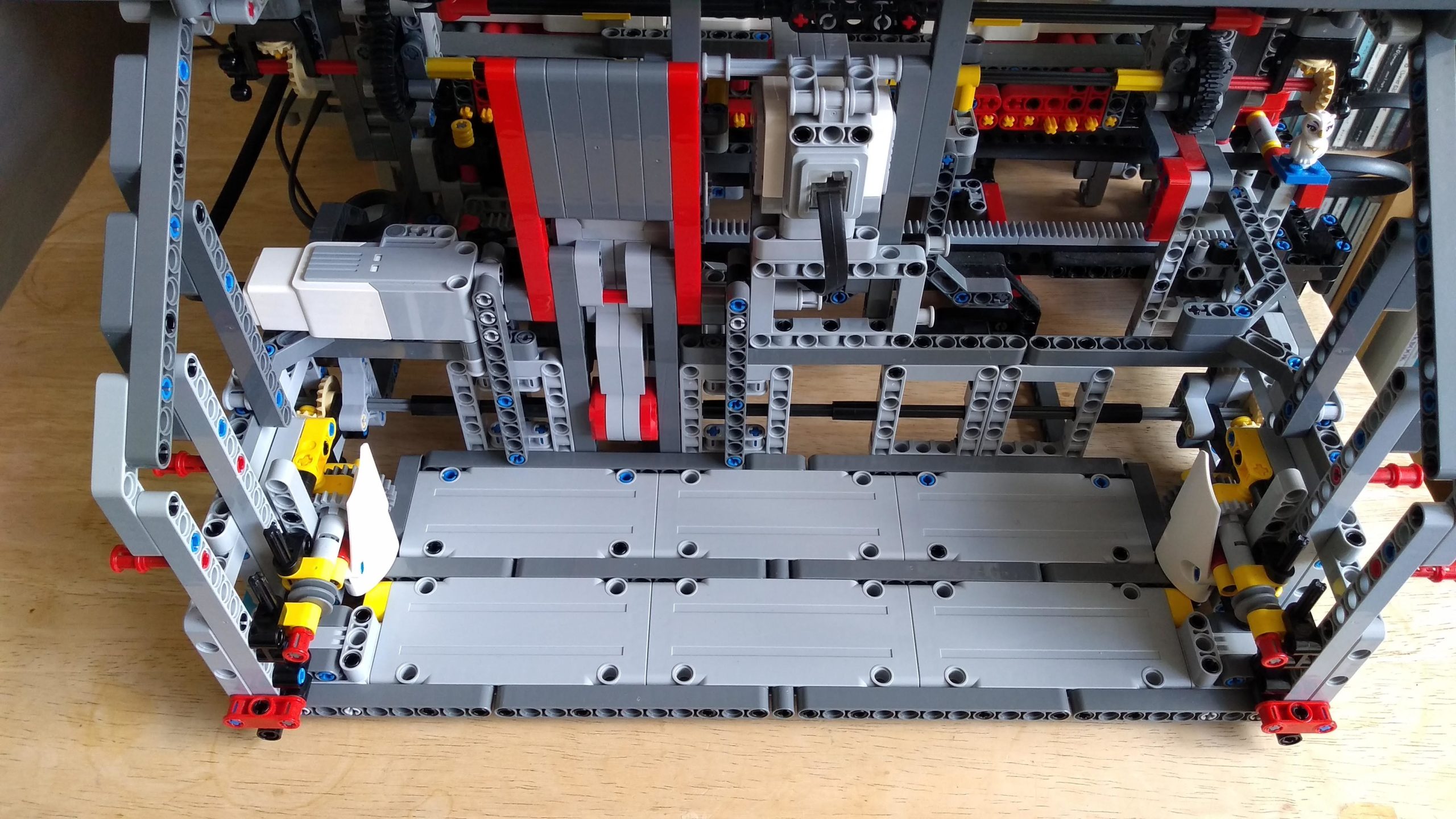
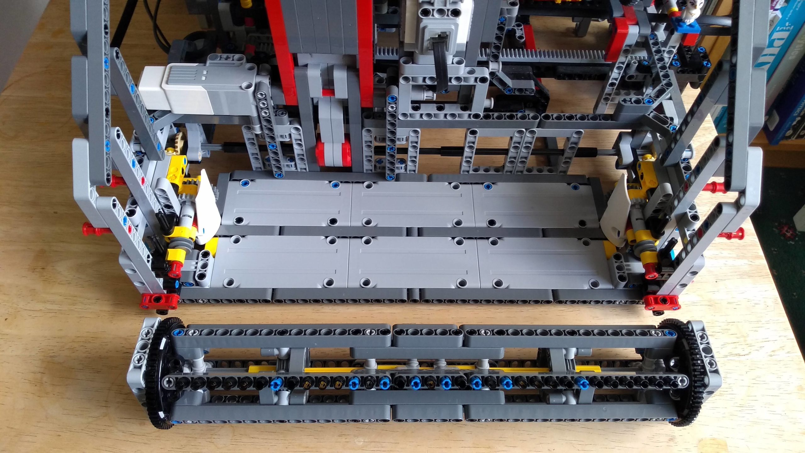
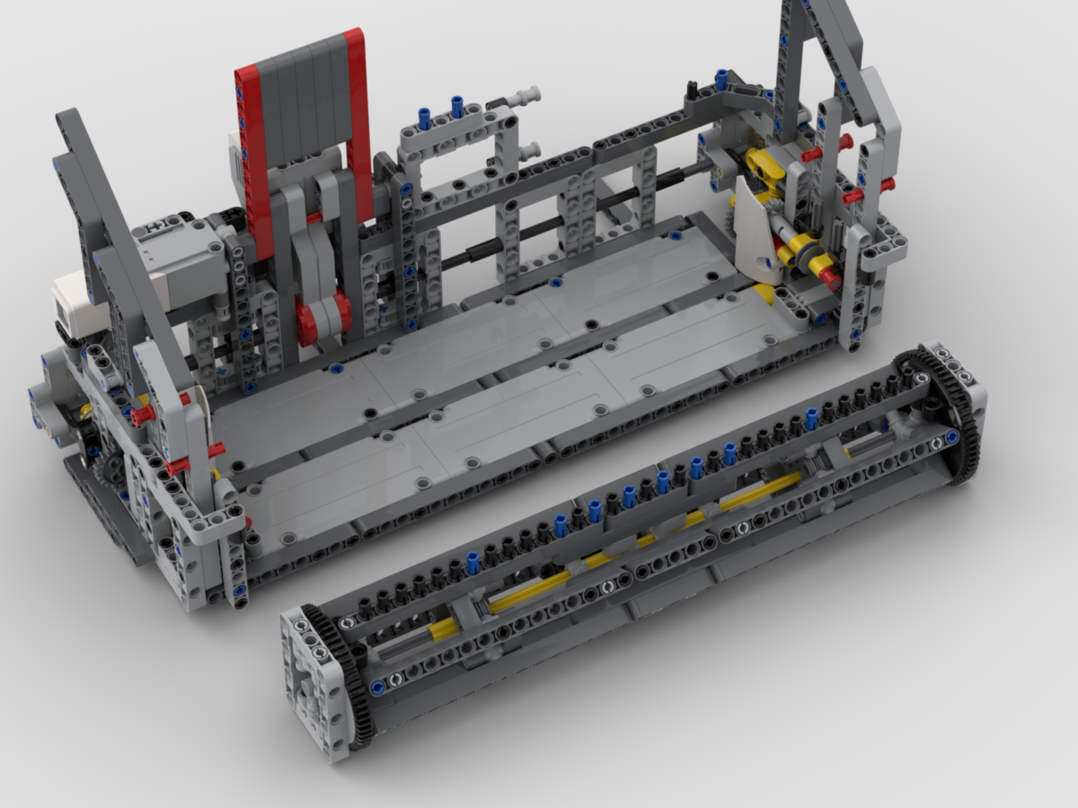
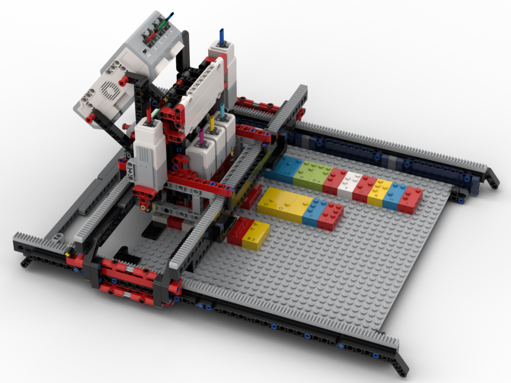
The Braille sensing mechanism (the ‘lift’ as I think of it) needed to move in both X axis and Y axis, so that the several rows of bricks could be placed on the baseboards supplied with the kit. The lift would be mounted on a bridge, allowing for Y-axis movement, and the bridge itself would move in the X-axis. The bridge took a few attempts to get right. Due to a combination of the mass of the lift and the force required to press in the switches resulted in flexing of the bridge, so this required a few revisions to get it rigid enough but not too bulky
One thing I had never realised about the EV3’s switches is that they trigger at the start of their travel, i.e. they don’t need to be pushed all the way in to trigger. Had they needed to be depressed all the way, it’s quite possible this model would never have worked. Due to LEGO being plastic, the parts are never perfectly aligned. This could have meant that one of the switches may have reached the end of its travel before either/both of the other switches had triggered. No amount of extra downward force could have pressed the other two as this switch would have blocked any more movement. Thankfully they trigger at the start, so it’s still possible to push down, thus enabling the neighbouring switches to also trigger.
Due to slight flex in the model, it’s not possible to have the motor wind the linear actuators to the same place per row of Braille. The middle two rows can require a little more force. To solve this the bot requires calibration on first use, and offers to calibrate on start up as well. Calibration requires that an L (⠇) brick is placed at the start of each row, then the bot tests each of those bricks. For each row the motor position for the last switch to activate is stored on disk, for repeat use, then when in use it drives the motor to just beyond the motor angle to ensure that all switches could be activated.
Accessibility
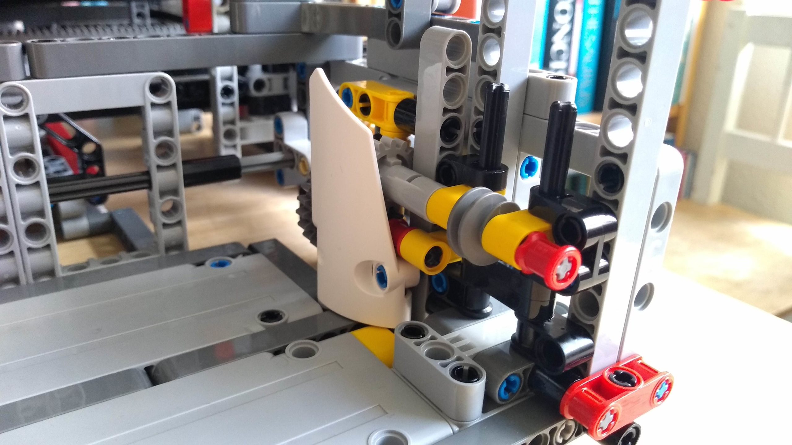
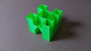
As I said at the start, I wanted this model to be accessible to the target users, so all instructions are read out as well as displayed on screen. All button operations have a small click to provide audio feedback, along with a relevant audio prompt, e.g. saying which row has been selected to read. To aid in placing the Braille bricks on the baseboard there are tiles on the first column. Subsequent bricks are simply placed next to the previous bricks. The EV3 has been oriented so that the speaker is facing the user so that it can be heard.
Video
As part of our group’s remix challenge we have to produce a video relating to our build. I opted to have the video show parts of the robot and it in operation. Since the bot converts the Braille to speech, I figured I’d have the voice-over performed by the bot as well (I’m never a fan of speaking on camera, and being a Brit I always feel that I sound sarcastic 😆). I also thought that it would be a fun little feature to have the subtitles show in Braille first and the wipe over to the actual text. The resulting video is below:
Build Instructions and Code
Build instructions: http://jander.me.uk/LEGO/resources/Braill3-BIs.pdf
Python code: http://jander.me.uk/LEGO/resources/braille.zip
The Python code needs to be run under Pybricks micropython, under ev3dev. This requires a microSD card. The official LEGO ev3dev installation can be found at: https://education.lego.com/en-us/product-resources/mindstorms-ev3/teacher-resources/python-for-ev3/
Operating Instructions
- On first ever run of the program, it will pre-generate all the pre-coded speech prompts. This is so that the program doesn’t have to perform the TTS step every time a common speech prompt is needed. It will only do this the once.
- On first run of the program it will insist on a calibration step. It will offer to perform a calibration on every other run, but it defaults to ‘no’. To calibrate perform the following:
- Put an L brick at the start of each of the 4 rows
- Press the centre button. This will then test each of the sensors and motor and store for future use
- Lay out the Braille as wanted. There are 4 rows that can be used. Select the row to be read with the left and right buttons, centre to read. Spaces between words can be either one or two columns of studs wide. Three or more empty columns will end the row of text.