Whilst we’re all in the position that we need to reduce social contact due to COVID-19, I have taken the opportunity to work on a couple of aspects about my Weav3r loom that I felt needed attention. I have definitely solved one of them and hope, when I can buy some parts, that I have solved the other.
Clicking Gears
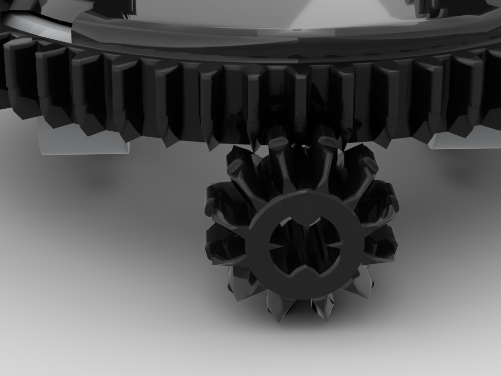
This is the problem I hope to have solved, but don’t yet have conclusive proof. Whilst working on the problem of the concentric drive I found that the mesh between the usual 12T gear and the 60T turntable was not particularly good. Looking at the image below it can be seen that the teeth of the 12T gear approach at quite a shallow angle to the 60T. This can be seen at the 11 and 1 o’clock positions – the teeth of the turntable appear to “dig in” to the 12T gear. This causes the mesh between these gears to sometimes be very rough.
When working on the concentric drive I found that the 20T gear is a much better mesh, but this requires a 1/2L offset which really just didn’t work for the loom. The other issue with using a bevel gear to drive the turntable is that the tension in the warp thread could feasibly be high enough that as the turntable rotated it would be pulled up and away from its drive gear which could also produce the same clicking problem.
The change to the gear chain has been to have the worm gear driving the turntable. This is a great benefit as the worm drive is a much smoother mesh and, also, it is not possible for the turntable to lift off the worm. To drive the 60T turntable with a worm gear I will need to use the newer 1L type – this is the part I don’t have, but have rebuilt with the intent to use.
The existing gear chain was: 1 • 20:12 • 1:24 • 12:60 => 1:72. This used one of the old 3L worm gears, halfway down the gear chain. To use the 1L worm at the end, with the same axle paths from the large motor, the gear chain is now: 1 • 20:12 • 24:24 • 8:16 • 1:60 => 1:72, so the same ratio. However, the additional 24:24 will have reversed the direction, so I must remember to adjust my code to reflect that.
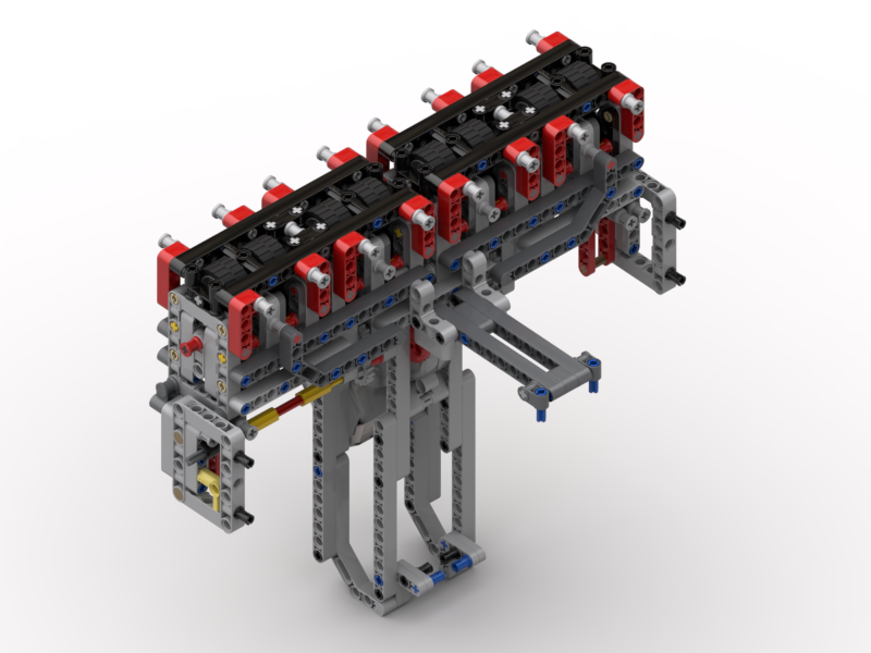
The new turntable drive now looks like the image below:
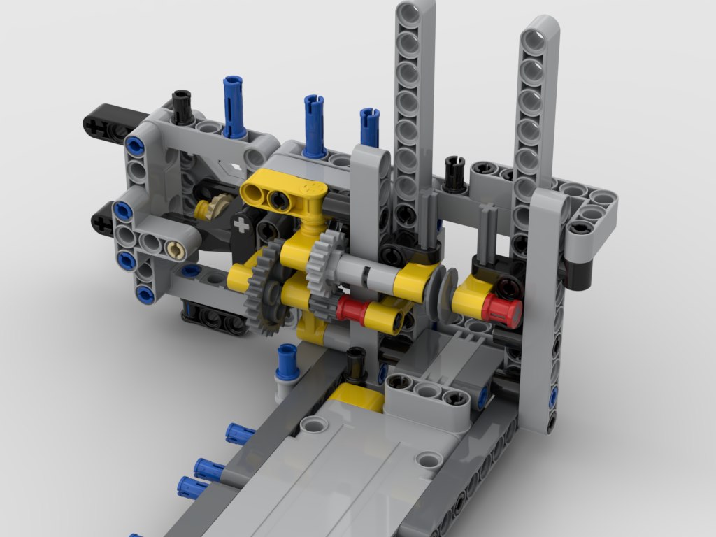
Detachable Drum
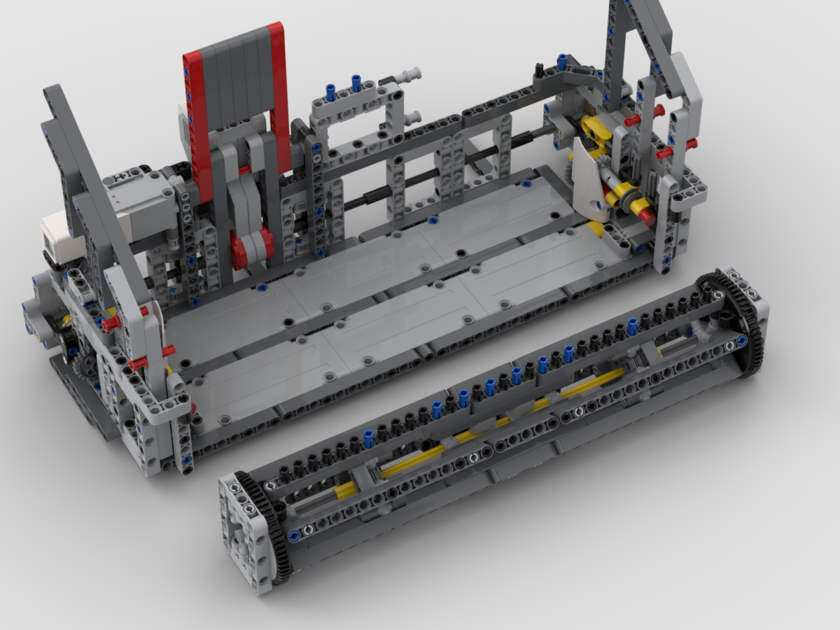
The original build’s drum was locked in to the structure. This meant that to remove the scarf, at the end of a day’s show, the whole thing had to be run in reverse for around 3m. This would take a remarkably long time, and was just extra wear and tear on the mechanism that could be avoided. So, another design criterion for this change was to make the drum removable, but at the same time retain its strong connection to the worm gear. This has, happily, been achieved.
The drum has a 5 x 7 open centred frame at each end which locks in just above the worm gear. In the image above it’s possible to see two 4L axles with stop either side and behind the worm gear. These lock in to the bottom of the drum’s end frame preventing any misalignment. The frame is locked in to place by two bush pins inserted from behind.
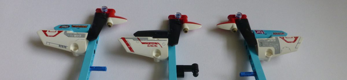
The drum itself has also been altered. The original was somewhat flexible and the pins along one “side” had a gap in them. The inner “hexagons” inside now have two pulley wheels inside to support them, making the drum more rigid. The structure has also been reworked to remove the gap in the pins. An added benefit to that is that there are 33 continuous pins, which equates to 32 slots between them, one per warp thread. An intermediate render, I’ve changed things a little since I made it such as the black bush pins are in the wrong place now, is shown below:
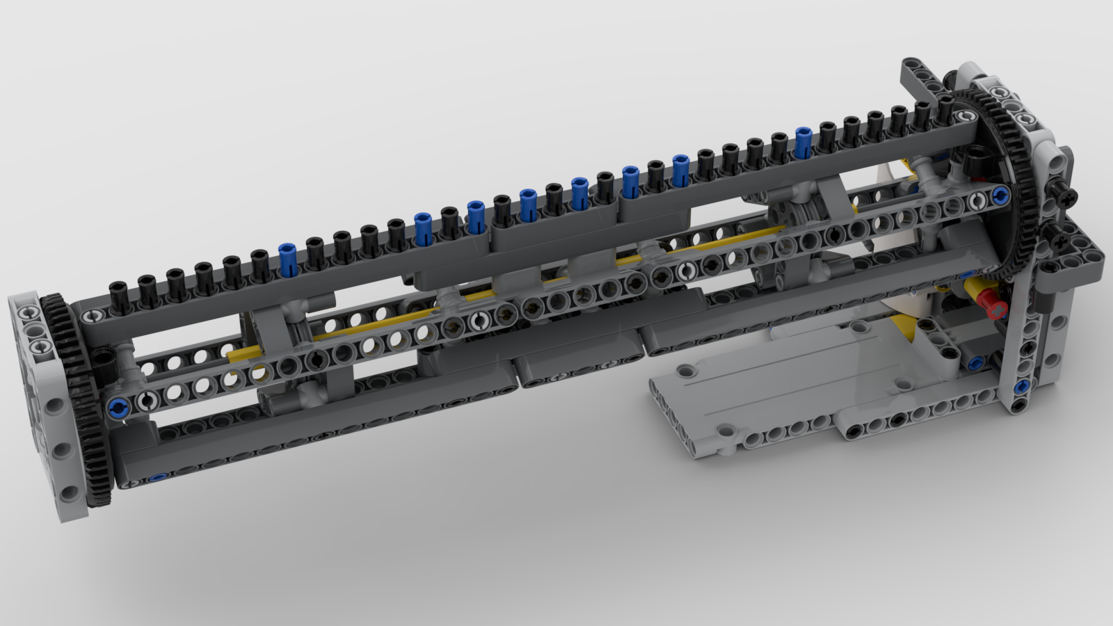
The entire front structure that encloses the drum is removable for transportation, i.e. for DHL to take it abroad 🙂 This has had some attention at the back of it, but that is more cosmetic and tidies a few things up. One humorous thing is that when I’ve detached it recently I’ve partially dismantled a section – I’d totally forgotten I’d built it so that I pull out 4 bush pins and the whole unit lowers down and forward!
Renders of the final structure with the drum installed, and removed, are shown below.


An animated render of the structure is below:
For those that may be interested, I’m posting the LDraw model. I don’t intend producing a PDF of BIs, but this model is in steps, so should be easy to follow. This work is released under the Creative Commons Attribution-NonCommercial-ShareAlike 4.0 International licence.