Over the past few days I’ve been rather nerd-sniped in to thinking about a system for passing two concentric drives through a turntable.
I’m starting to think on ideas for a bot that I plan to build later this year. This bot will need an “arm” attached to a turntable, with two motorised functions attached to it. There will be driven functions on either side of the turntable and it must be able to rotate an indefinite number of degrees, so passing cables through the turntable is not an option. This leads to the only conclusion that the two driven functions on the arm must be driven by axles passing through the middle of the turntable.
Two parallel axles don’t work, as when the turntable rotates, how does one keep the gears attached? The answer is to use concentric drive shafts. This can be done either using driving rings, or a 16T/24T empty differential. The former is no good for my bot due to the ~90° backlash in a driving ring, and thankfully I had one of the latter!
Maintaining Alignment – Unity
The next issue is what I’m mainly blogging about – when the turntable rotates, the concentric shafts need to rotate in unison. I could achieve that, to pretty good success, by driving all three motors at the same time at appropriate ratios – but where’s the fun in that? Instead I’ve opted for using two additional differentials as adder/subtractors on the input shafts for the concentric drive. So, as the turntable rotates the two differentials add/subtract a proportional amount from the other two inputs, so it all rotates together. It’s hard to describe, but it does work.
For this all to work, for each rotation of the turntable I need to have a half turn of the differentials – that results in a full rotation of the output side of the diffs. That turned out the be easier said than done. The turntable has 60 teeth, and the diffs have 28 teeth. So I needed a 60:14 ratio. Thankfully I have a SPIKE Prime, which has two of the new 28 teeth gears 😀 This works out to be: 60 *28/36 * 12/20 * 16/24 * 12/16 = 14. My resultant mechanism looks like below:
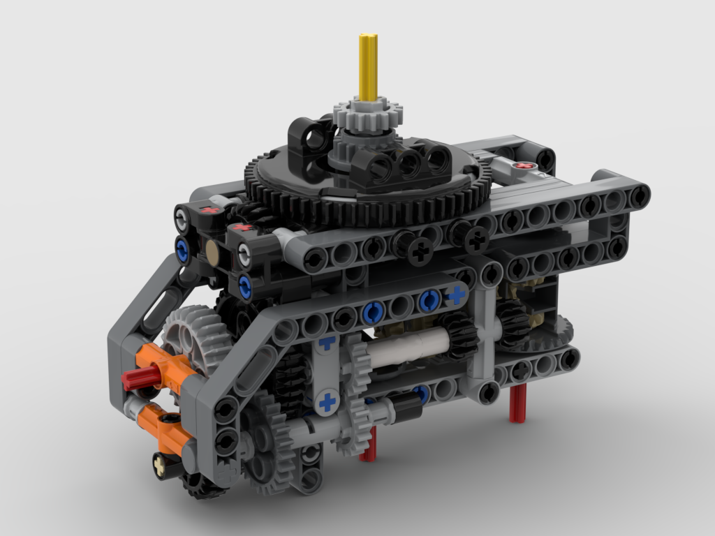
The two input shaft, red axles, at the bottom drive the two 16T gear outputs above the turntable. The red input axle on the left drives the turntable. This is as compact as I could make it.
Gearing Issues
One thing to note is the 1/2 offset 20T bevel gear that drives the turntable, as an idler gear. Normally a 12T bevel gear at normal spacing would be used. Originally I did have that but it was incredibly noisy and “crunchy”. After lots of inspection under various lights, even trying a bit of silicone lubricant I realised the issue – the 12T gear was binding up against the teeth of the 60T turntable due the the teeths’ angle of contact. As a “new” tooth from the 12T gear approaches one of the teeth on the 60T gear, the angle is too steep, resulting in the 12T gear pushing the 60T gear up rather than across. This would explain issues I’ve had with my loom clicking loudly at times – the front cloth winding roller is also a 12T/60T combination. The same must be happening there. The answer here was to use a 20T gear, but that required a 1/2 offset which was an interesting challenge to fit it, but it now works a treat.
Build Instructions
I’m a few months away from actually implementing my ideas – I have lots of things for the loom to do first – but at least I have got my nerd sniped brain over this problem. I’ve made an LDraw model of it, but haven’t got the time to turn it into full build instructions. This is being released under the Creative Commons Attribution-ShareAlike 4.0 International License and is available from: