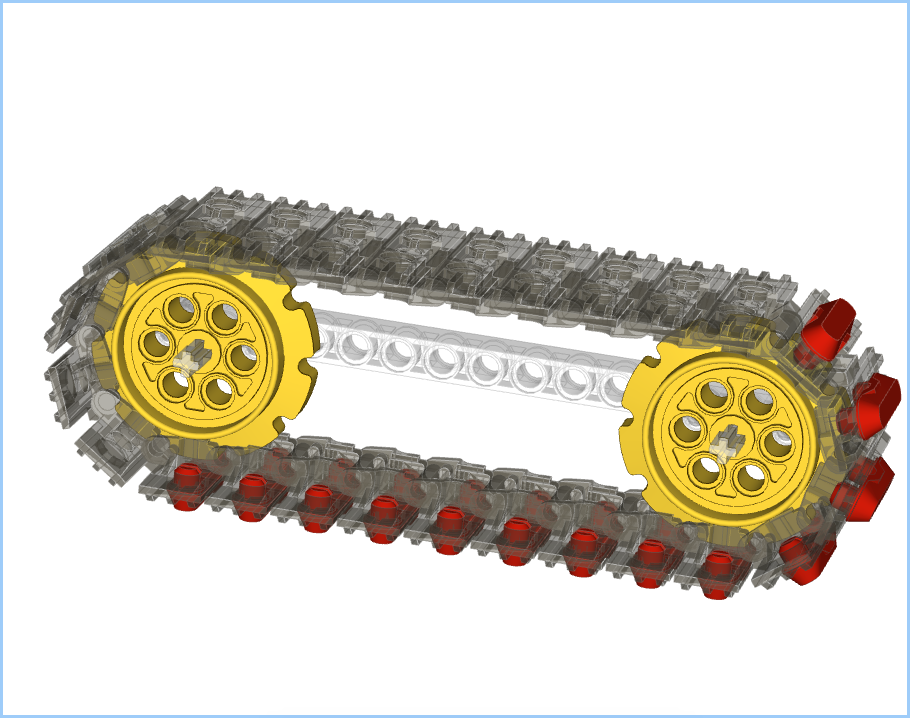
Sprocket Orientation
When building up a model in Bricksmith it’s important to consider the orientation of the sprockets. You’ll want them rotated such that the treads sit in the notches correctly. Generally the sprockets are going to end up in one of two orientations, 90˚ rotation between them:
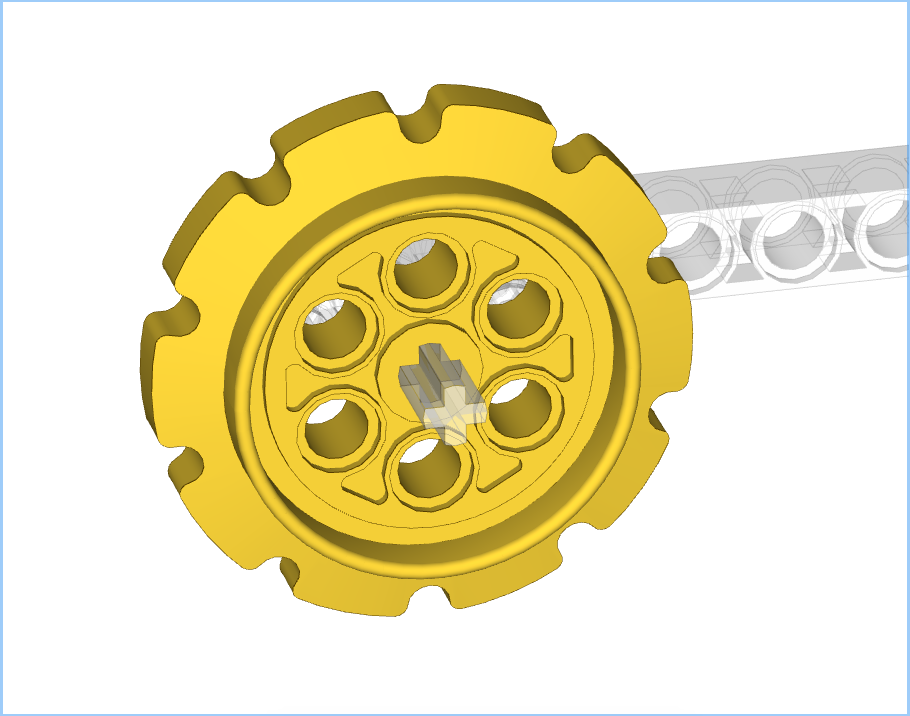
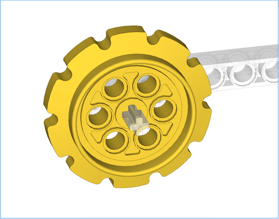
The notch at the top is better as the treads will sit in the notch easily, whereas the notch at the side will require fine-grained movement to get the initial tread in place. For this particular post I will focus on the latter, i.e. notch at the side. Although this requires more initial set up the rotation of the treads is simpler. I will cover the other variant in a third post.
Rotation Controls
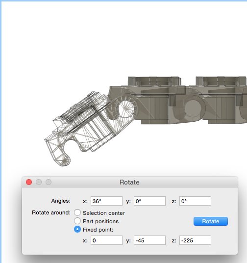
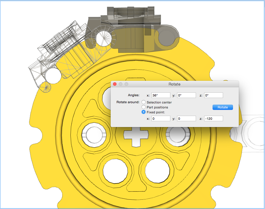
Since we’re wanting to place treads on the large sprocket, in my example, we’re going to want to rotate by 36˚. This is because there are 10 notches in the sprocket, so 360˚/10 = 36˚. The rotation controls are reachable from the Edit menu, and give a control box as below:

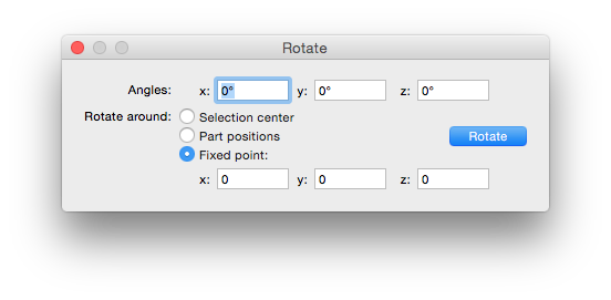
All of our rotations will be around a fixed point.
Initial Tread Placement
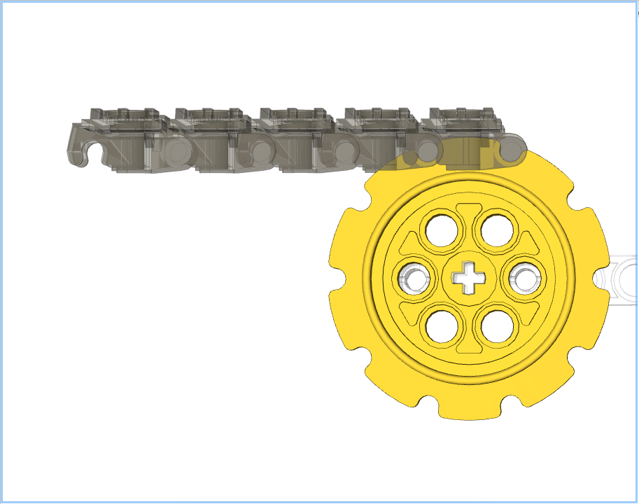
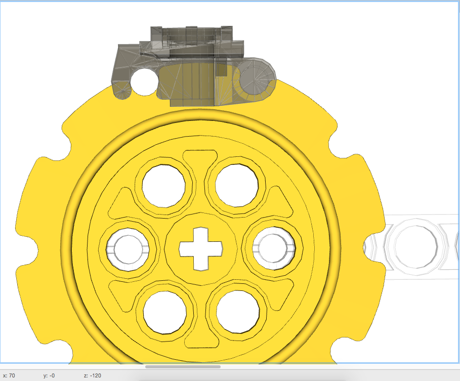
The first thing to do is align a single tread with the sprocket. This is relatively easy, but in this orientation will require the fine grid for movement. The first tread ought to look like:

How I Used to Do Treads – aka “Introducing Cumulative Error”
When I first started to model treads manually I’d start with a line of treads which I’d “bend” in to place:
I would then select the first tread and rotate it about its pin. The coordinates of this pin can be found by moving the pointer around over the pin and observing the coordinates shown at the bottom of the Bricksmith window:
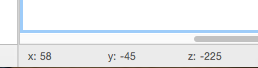
You’ll notice that two of these values change as the pointer moves but the third, in this example the x value, doesn’t. The two that change are the coordinates of the line passing through the tread’s pin.
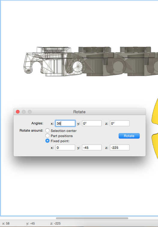
Next I select the the tread I have just rotated and its neighbour. I need to rotate both of them around the second tread’s pin. I know that the pins are 30 units apart, so I already know that the coordinates will be 0,-45,-195 without needing to check:

I now simply work my way back along the treads rotating around x=0,y=-45, and z=: -165 and -135. The result of this is:
This all used to make sense to me as the simplest way of doing this. However I started to notice small errors in placement. This can be seen in that the first tread doesn’t quite sit in its notches, a close up is below:
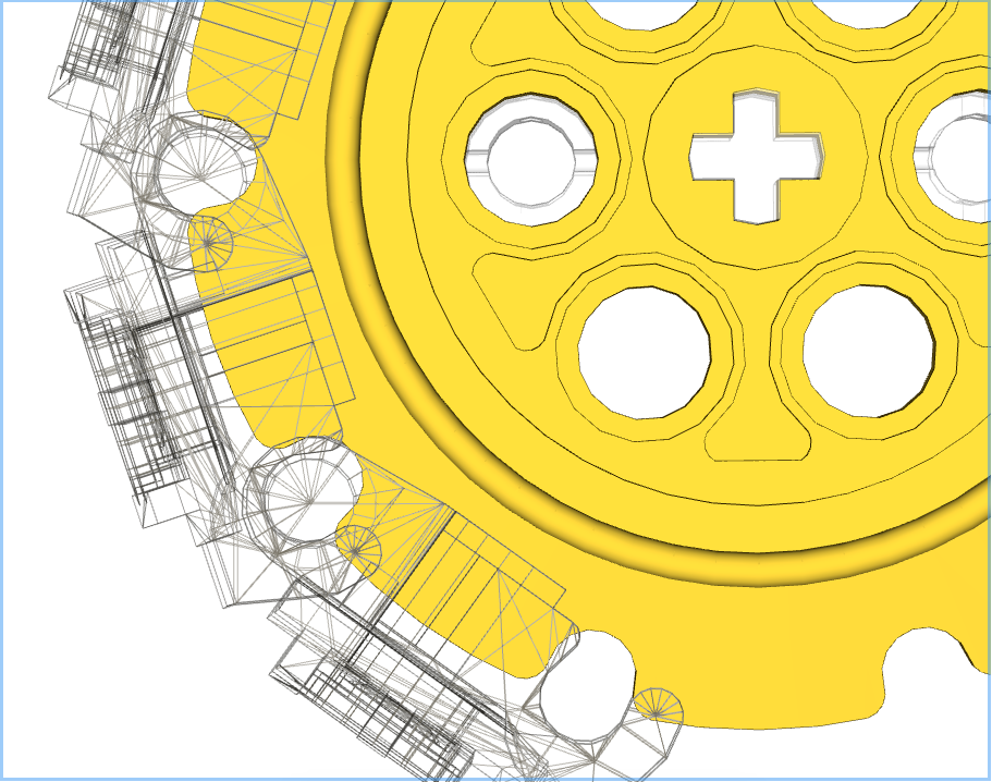
This is due to cumulative errors appearing. The first rotation is okay, but subsequent rotations slowly add errors to the placement. This first link has undergone 4 rotations around 4 different fixed points resulting in a small drift.
Being the perfectionist I am, this wasn’t acceptable, so back to the drawing board.
Individual Treads – aka “Doing it Right”
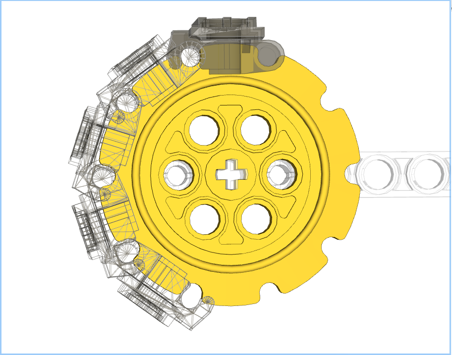
This time around we’ll only perform one rotation per tread, thus removing the cumulative errors. To achieve this copies of the top tread will be made, and placed in exactly the same spot, i.e. select tread, then cmd-C and cmd-V. This can just be seen in the image below with the wireframe inside the other tread:
This tread will now be rotated 36˚around the centre of the sprocket, not its pin:
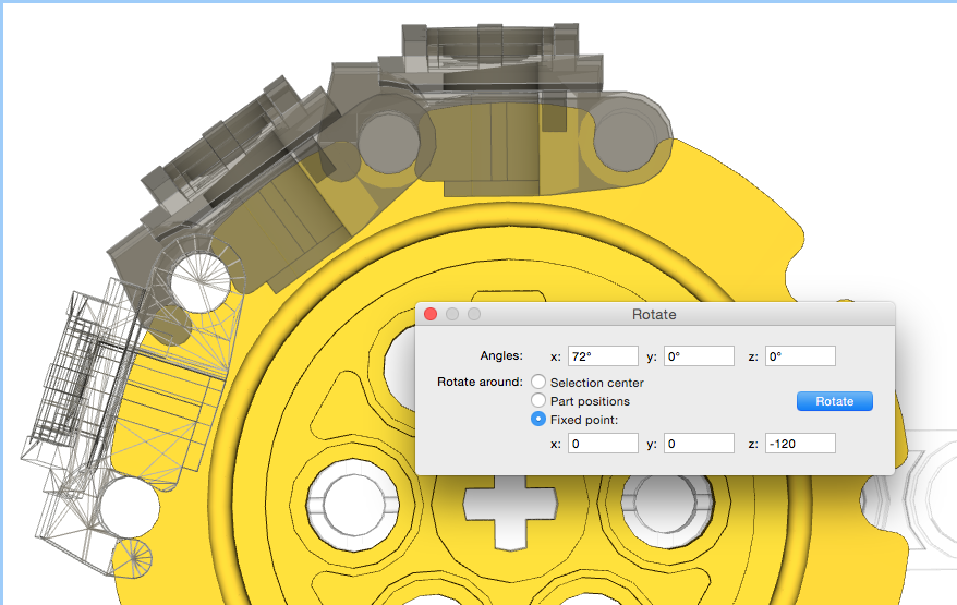
This will now be repeated, copying and pasting that top link, then rotating by 72˚, 108˚, and finally 144˚:
Treads with Rubber Feet.
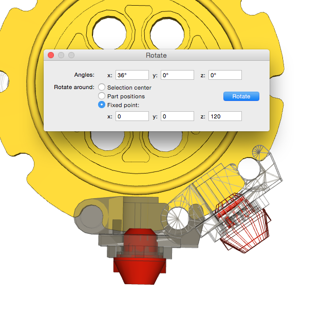
One of the comments I made in Part 1 was that LSynth didn’t support treads with rubber feet. To do this the first tread will need a rubber foot located with it, and then those two together can be copied and rotated as above:
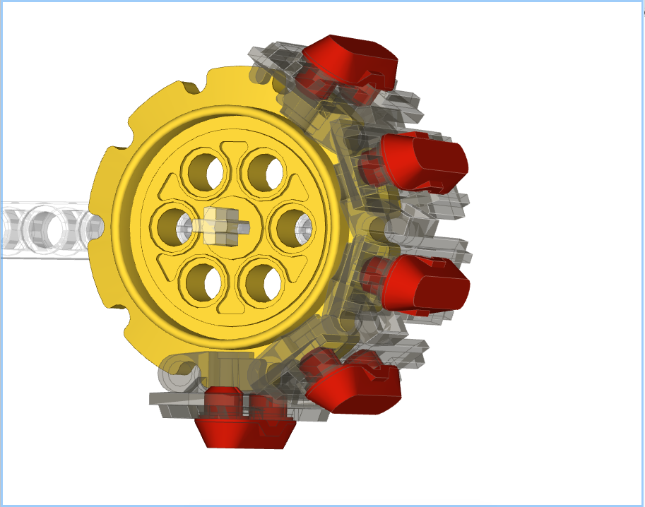
Completed Treads
Once the sprocket treads are in place, the top/bottom treads can be placed between the sprockets. For simplicity I copy and paste the initial tread placed on the sprocket:

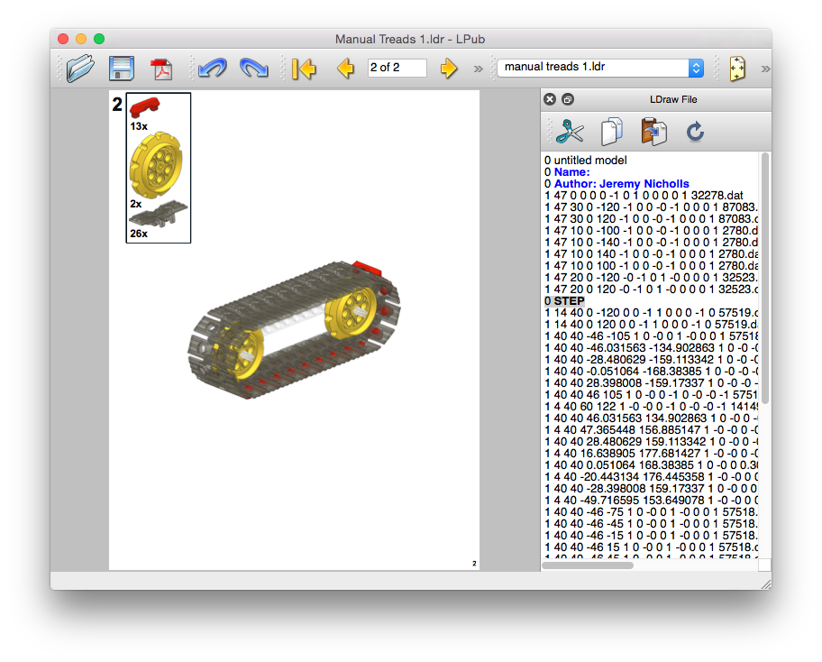
LPub4 Parts List
Another comment I made in Part 1 is that the LSynth structure doesn’t show up in the parts list. Since the treads placed via the methods above are normal elements there will be a valid parts list shown both on the page and in any Bill of Materials:
I hope this makes sense. Feel free to leave comments if I need to make anything clearer.
One thought on “Bricksmith and Treads – Part 2”