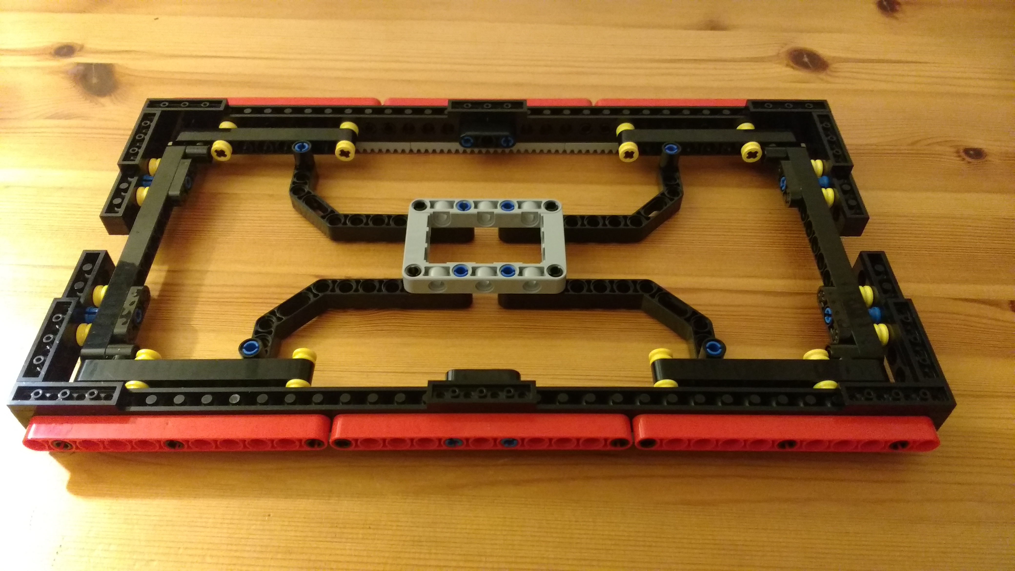
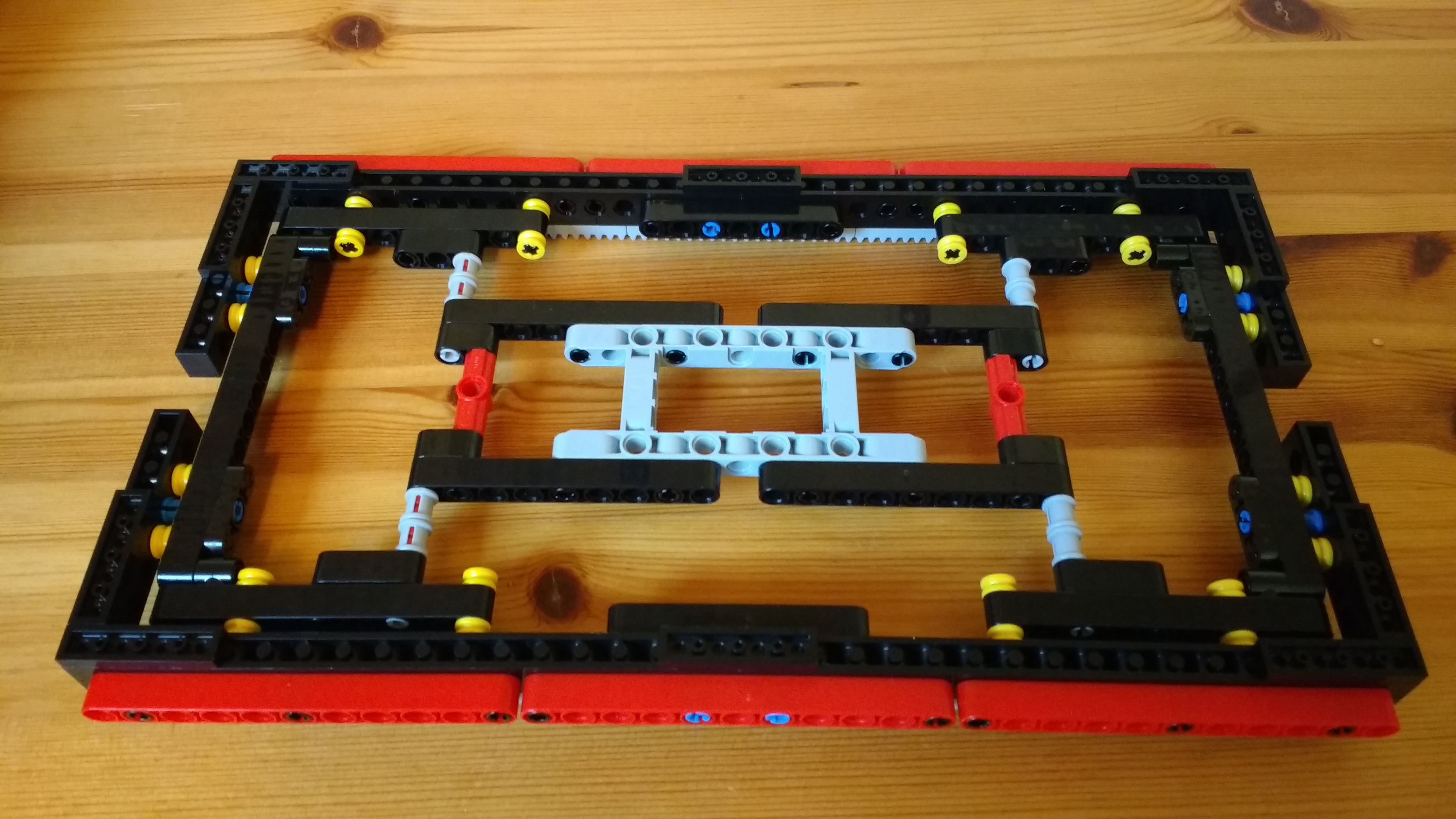
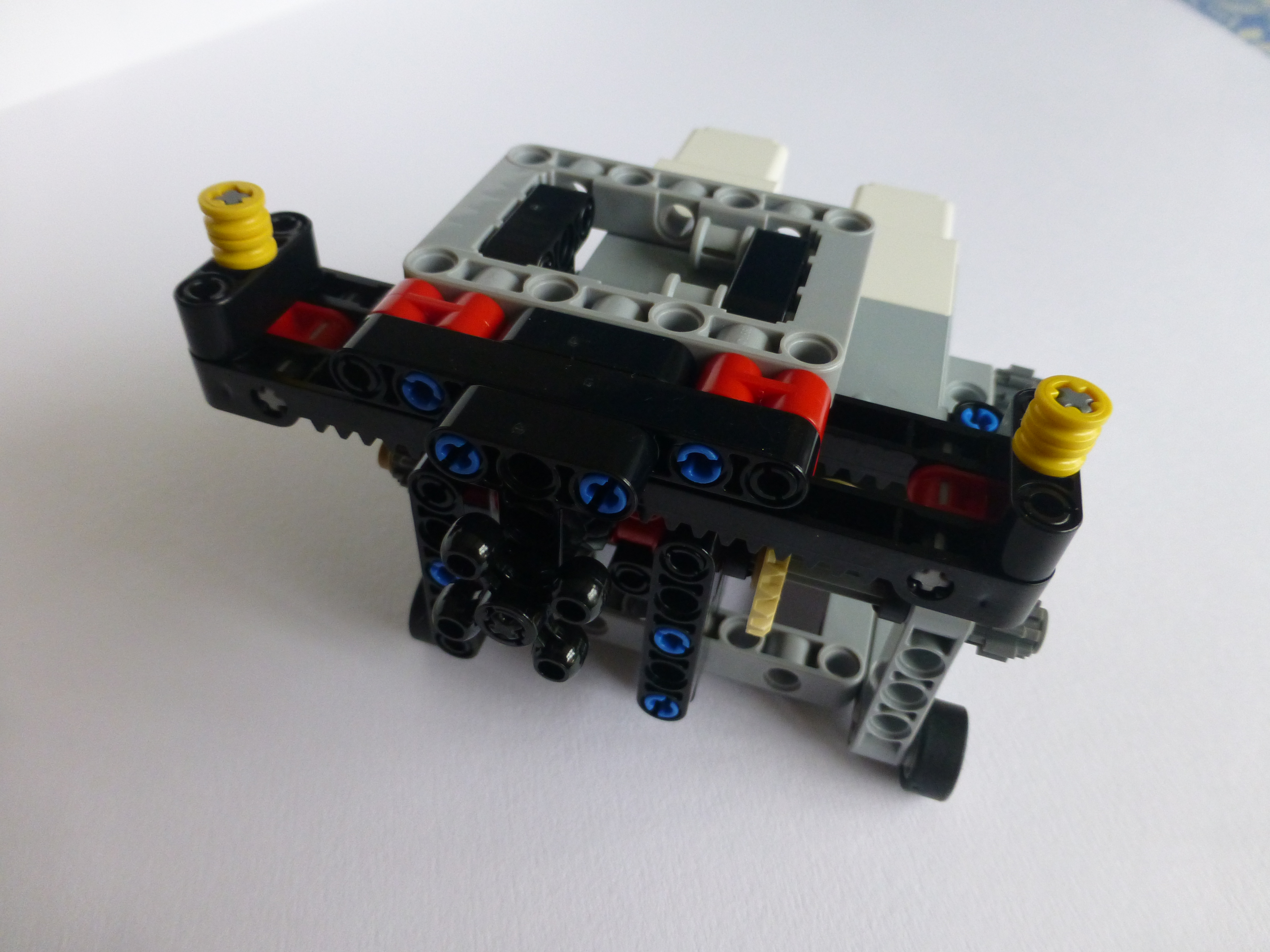
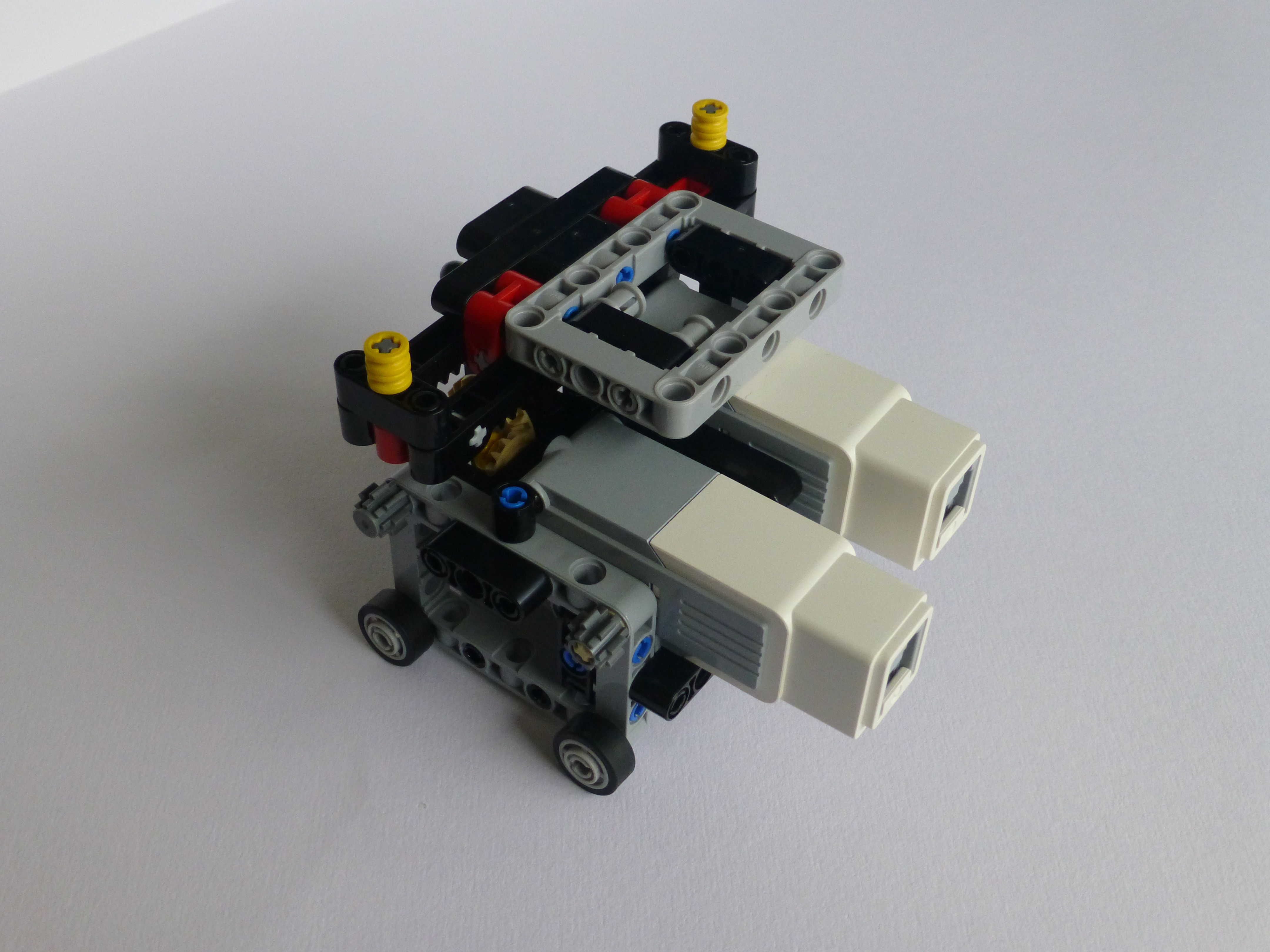
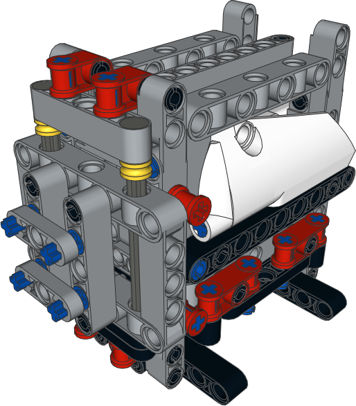
Whilst preparing for Bricktastic I developed a new, and hopefully better, pen holder for my Plott3r. This holder is a little heavier than the original, and somewhat more solid. This ought to remove some of the small erratic movements from the plots.The PDF for the building instructions can be found at:
It should be noted that the pen holder will need to be built on to the tracked section, it cannot be clipped on like the original. Build the base, attach it to the tracks, then clip the front and back sections on to it.
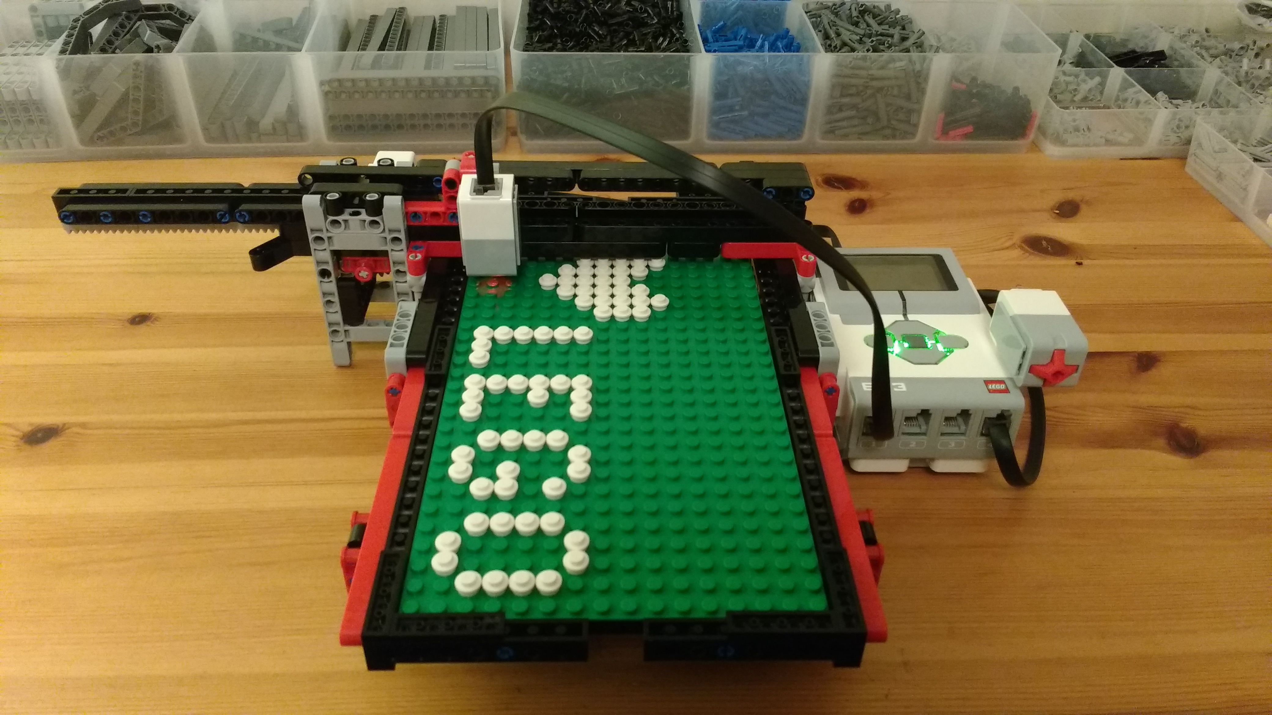
Okay, so I’ve been rather quiet on the blogging front for a few weeks – that’s because I’ve been working on getting my Plott3r to write out text:
ASCII Text
Here’s a video of it taken a little while ago (prior to some of the improvements I’ve made):
This has been rather a journey of discovery. I’ve blogged previously about getting a bluetooth message to the EV3 and how I needed to work out a font.
Font
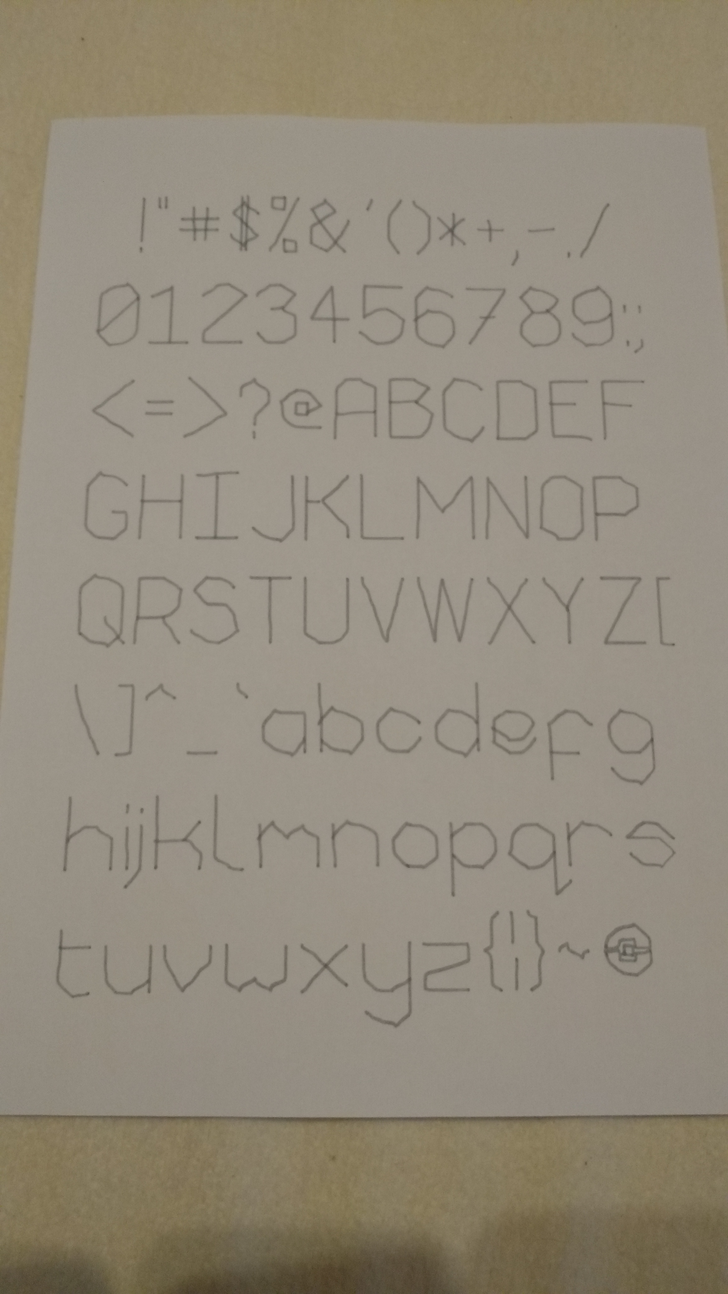
The font itself didn’t prove to be that tricky to work out; it’s mainly been planned out on 5mm graph paper and simply converted into coordinates. I’ve tried to have it write the letters as a Left->Right writer would, so starting on the left side of each character and probably ending on the right. This way moving the the next letter doesn’t involve a lot of travelling.
Backlash Correction
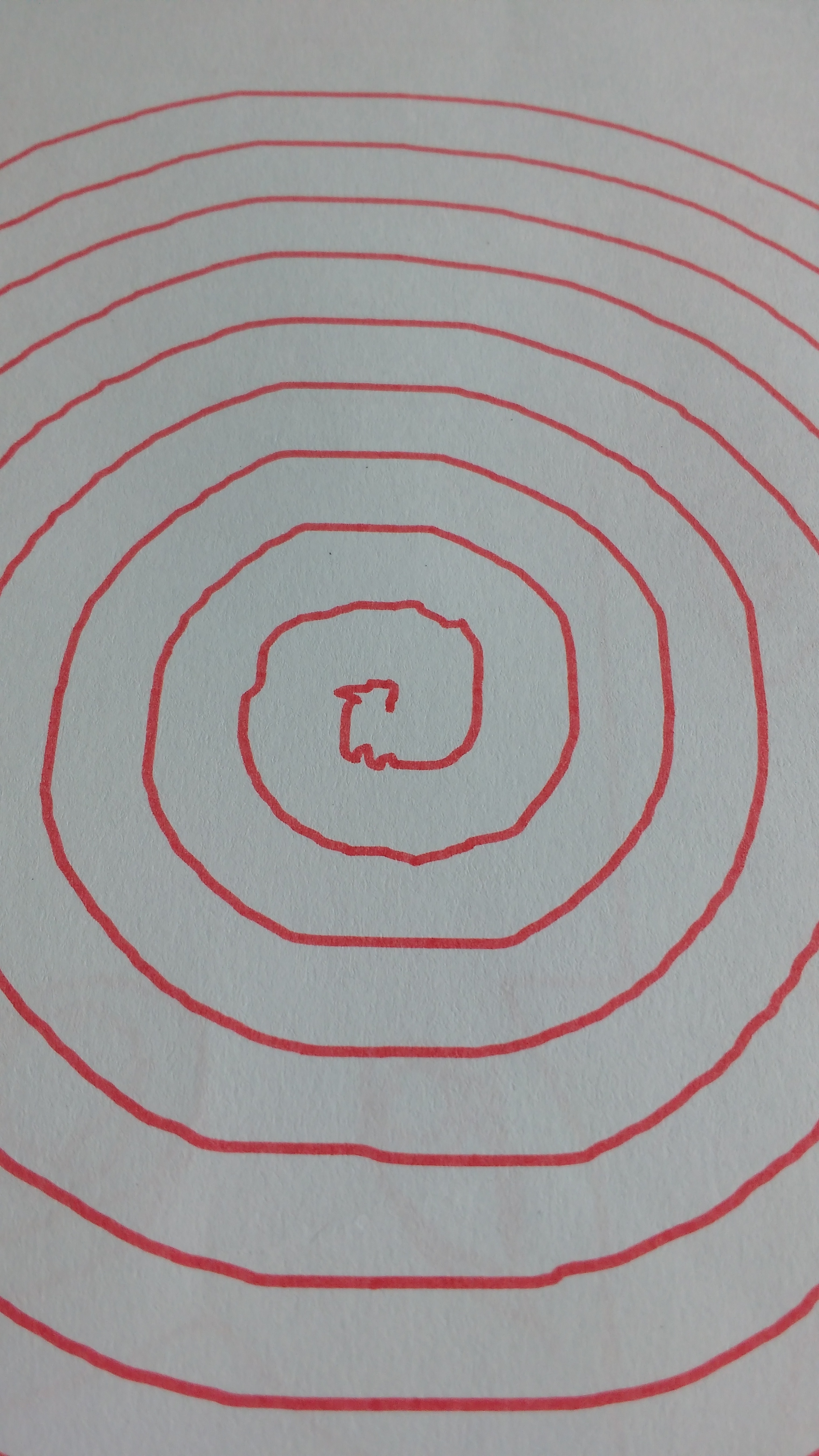
One thing my Plott3r has, is an effort to manage backlash. Since the paper and pen change direction regularly I have a system that pre-moves the paper/pen a little prior to any change in direction. One thing I hadn’t realised before is that if I want to move a really small amount I could overshoot where I wanted to be just in my backlash correction. This would cause some oscillation around the correct location in some cases. For example, look at the centre of the spiral below:
Backlash over-compensation
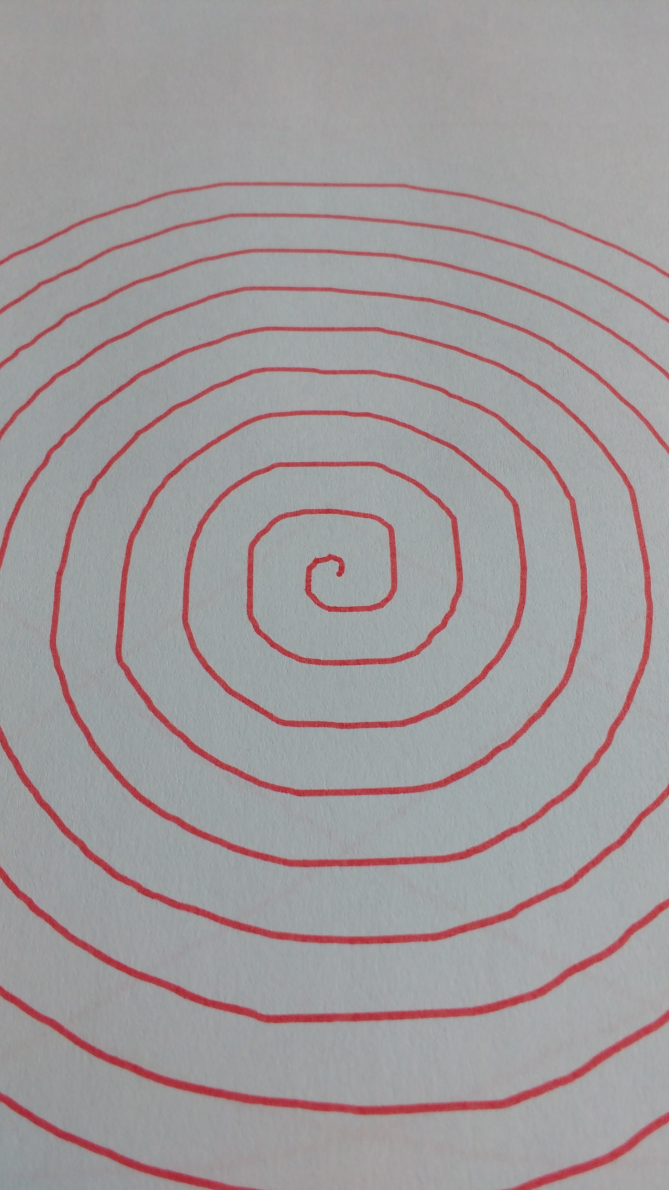
The centre of the spiral is crooked due to the pen “seeking” around the correct location. My solution to this was to measure where I was before the backlash correction, and after. If I had overshot, then I did not move that particular axis. The results of this improvement on the spiral are below:
Overshoot corrected backlash
Android App
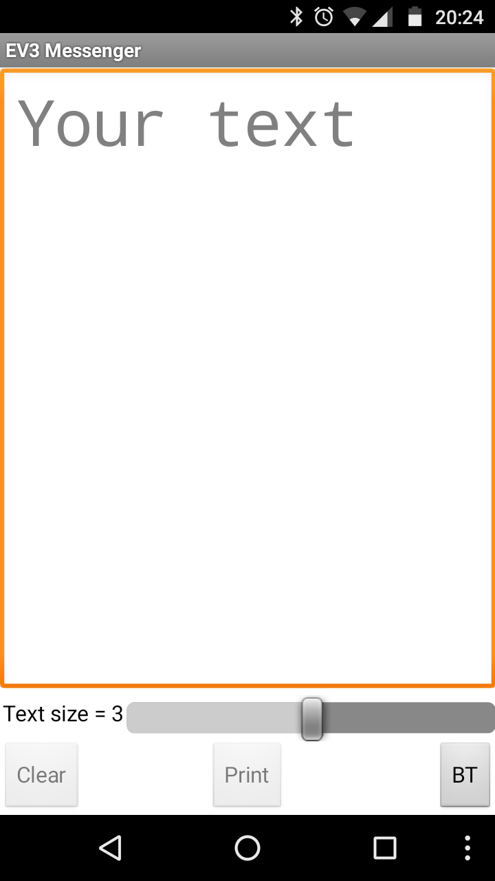
I wanted to be able to send a message from a spare Android phone to the EV3. Here’s where App Inventor 2 came in. I had to learn how it worked, along with learning its Scratch-like language, and implementing some fundamental routines, such as storing an IEE754 float. The current instance of the application looks like:
EV3 Messenger
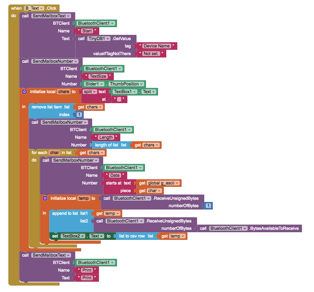
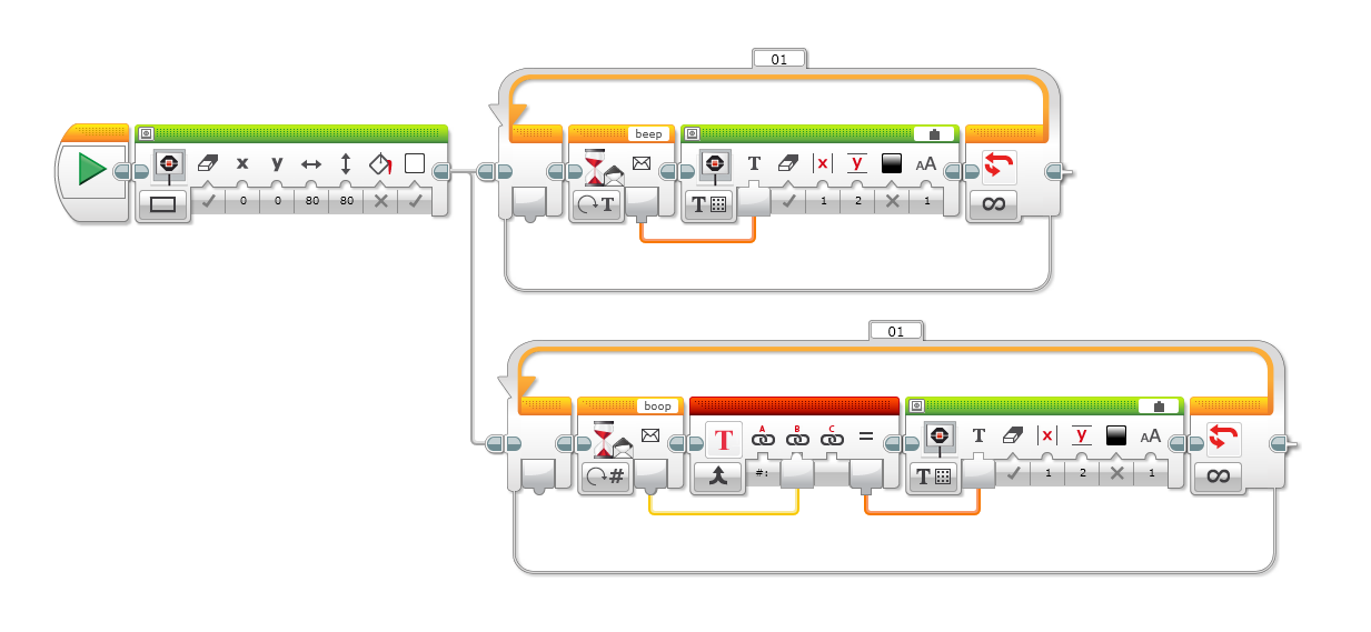
The user can simply choose between 3 text sizes, and then write their message and press “Print”. The BT button is used to set up the Bluetooth connection and the name of the sending device; this is needed so that the EV3 can acknowledge message it receives. I found that if I didn’t ACK the messages there was a race condition whereby I’d get duplicate values with the second “overwriting” what the first should have been. The core code of the messaging app is below:
AI2 Core Code
At the start of the block you can see it send its name, and towards the end of the block it waiting for a bluetooth message. It doesn’t care about the contents of the message, simply that it got one. The EV3G side of the code is as below:
EV3G Messenger
What’s not shown is the plotting code as that’s quite complex. It keeps a tally of the location of the last plotted character and works out if the next one will fit; performing <cr><nl> if needed. The font is variable width, and has a small amount of “kerning”, so that letters such as ‘j’ and ‘q’ can overlap the inter-character space.
Letter Sizes
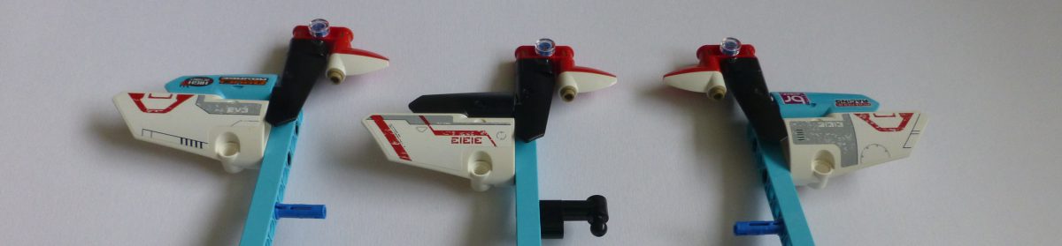
I originally was only going to have one letter size, but this would allow for only around 11 characters per line, which isn’t a lot. Shrinking the letters will result in more artefacts, which I’ll come on to later, but I think it has a certain “hand writing” charm:
Three letter sizes
Artefacts
There are a few artefacts that I’ve tried and tried to remove. I now think I’m simply fighting with the simple fact that it’s made from LEGO bricks and I can only realistically get a certain level of accuracy in the way I’ve built it. The main artefact left is as below:
Artefacts on 0, G, Q et al
If you look at the top and bottom of the 0 (zero), G and Q, there are small overshoots on one side of the diagonal. I think this is down to using Tank Move and the Y axis motor overshooting the target before moving back a little – a result of the internal PID controller.
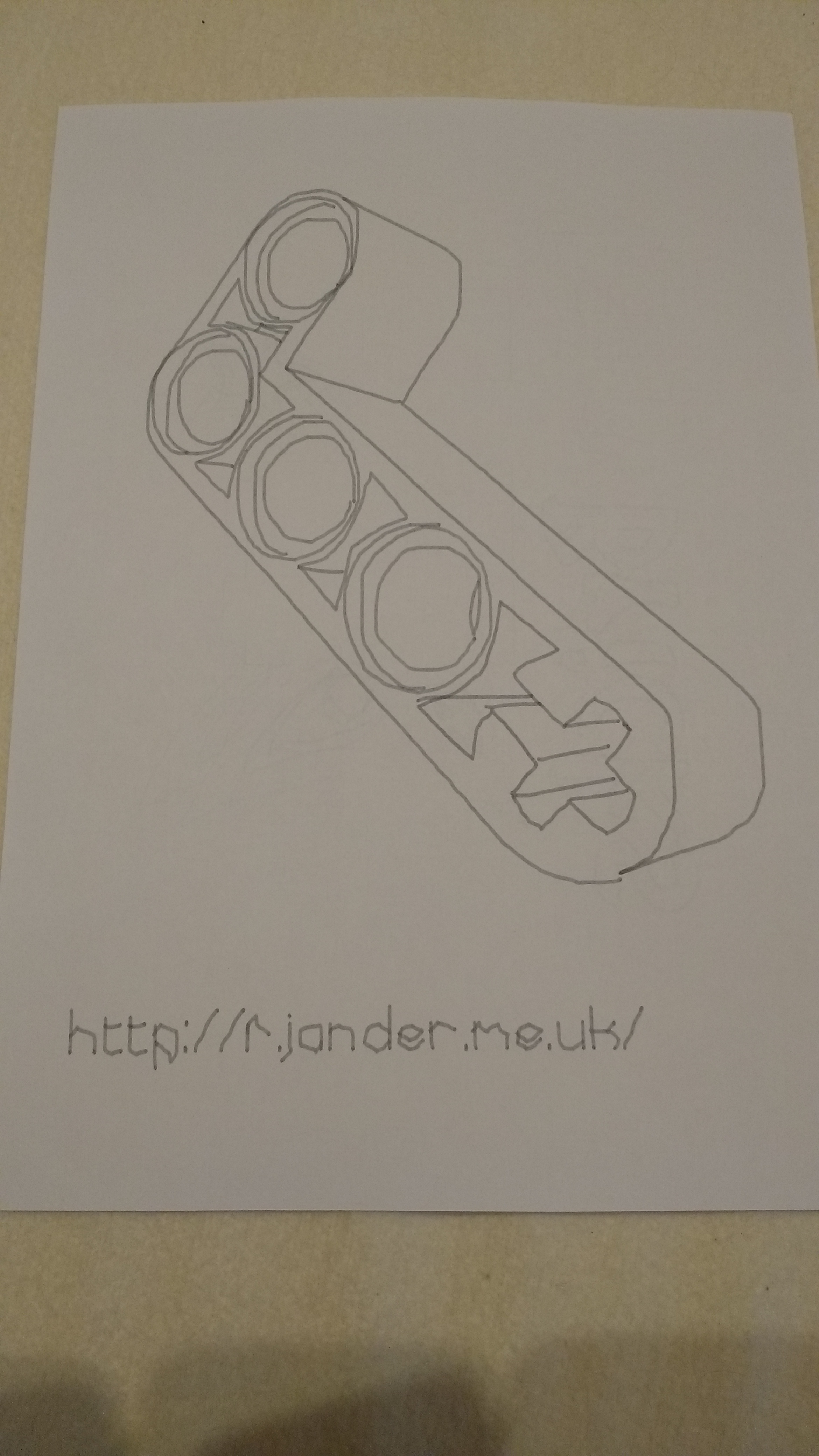
Signing Off
I’ll be showing this off again at Bricktastic this year, hence all this work. I’m pleased that, due to my desire to plot text, that the backlash control is better. I figured that I’d have the Plott3r do one more thing. It now “signs” its plots with the URL to this blog 🙂
Signing off
I now need to put this to bed for a bit whilst I check that all the other models still work. Then I need to get back on with my Loom – I need to do a little bit of programming for that ready for it to be shown off too.
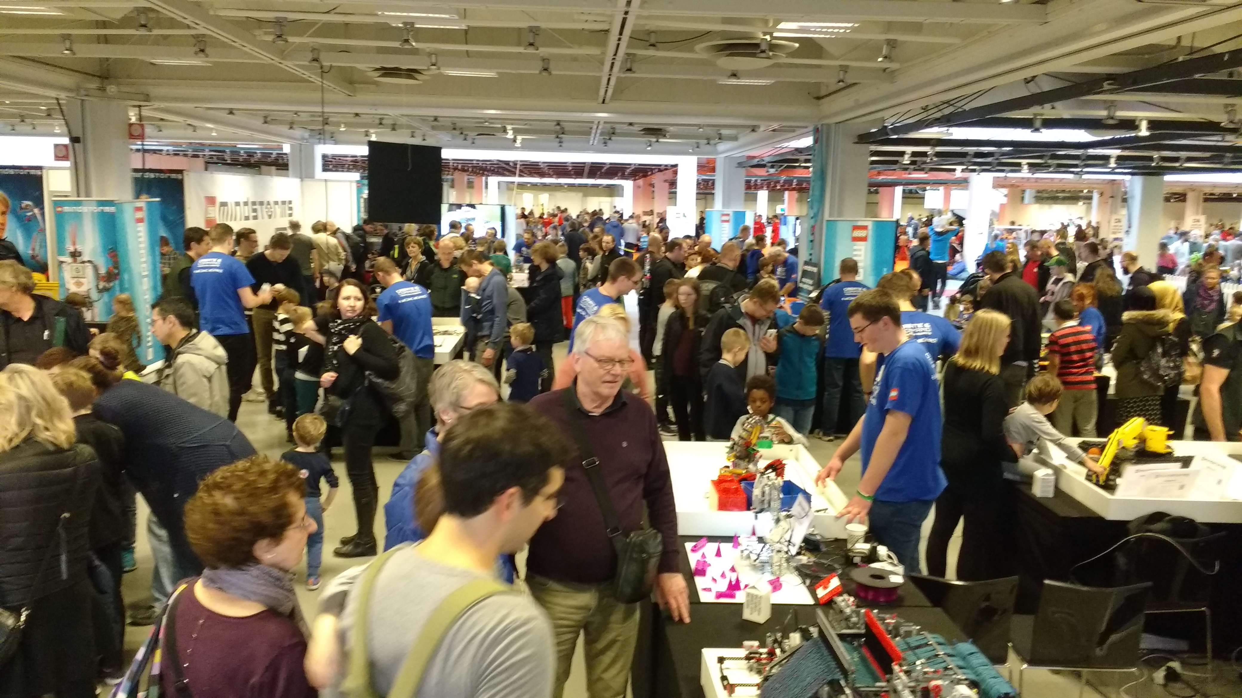
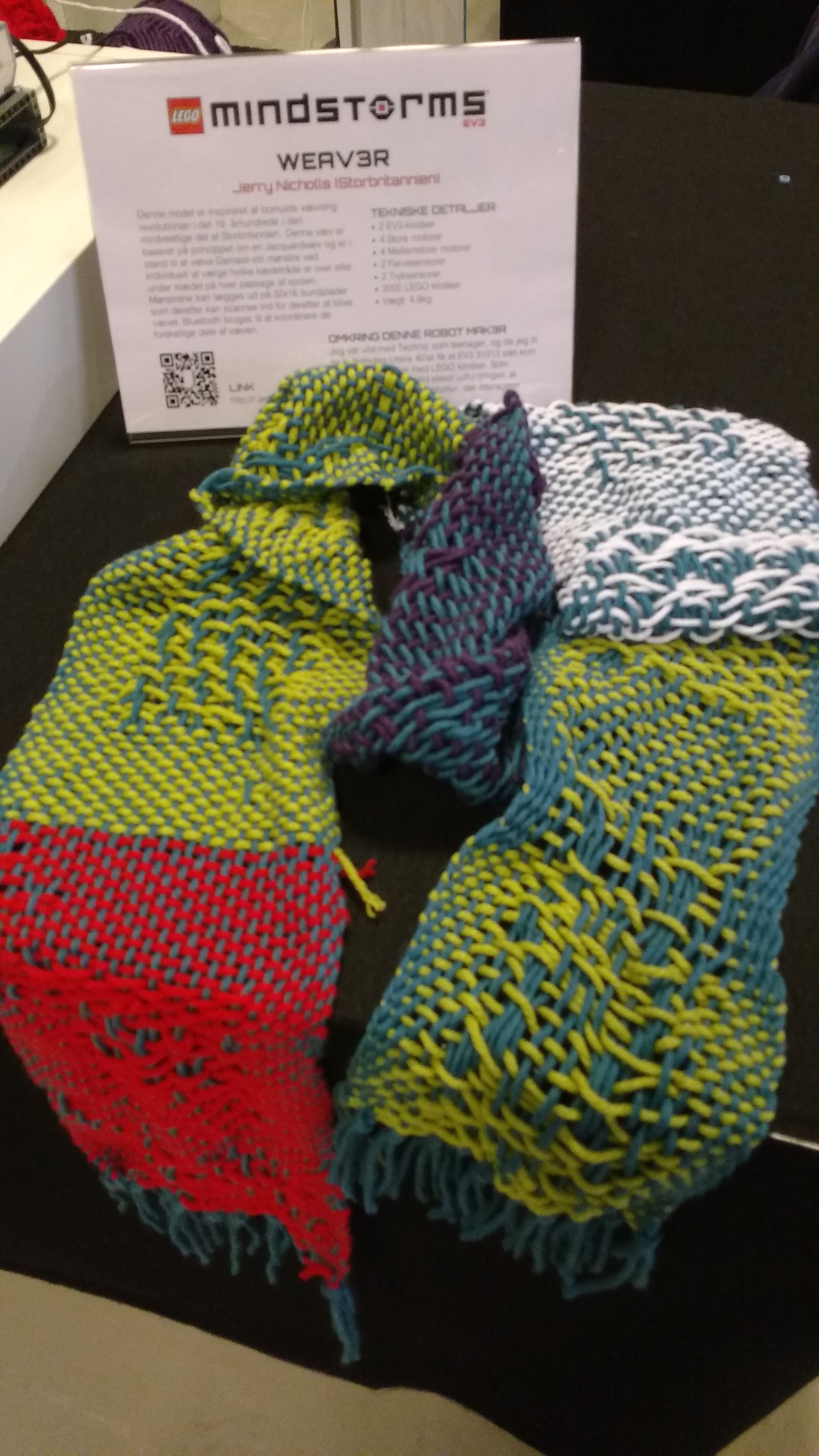
My Weav3r loom and I were invited to exhibit at the MINDSTORMS booth at LEGO World 2017 this year – what a blast!
Lots, and lots, and lots of people.
I had a deadline of the end of January to get the loom built and mainly functional in order to get it shipped out to Denmark. So, lots of hours in my attic across New Year, and coding in the last week of January to get it ready. One thing I did learn is that LEGO axles that need to slide, as opposed to rotate, do not mix well with traditional English Christmas cake! I managed to get icing on the axles which then turned into adhesive goo, preventing the heddles from setting – oops!
Set out on the night before.
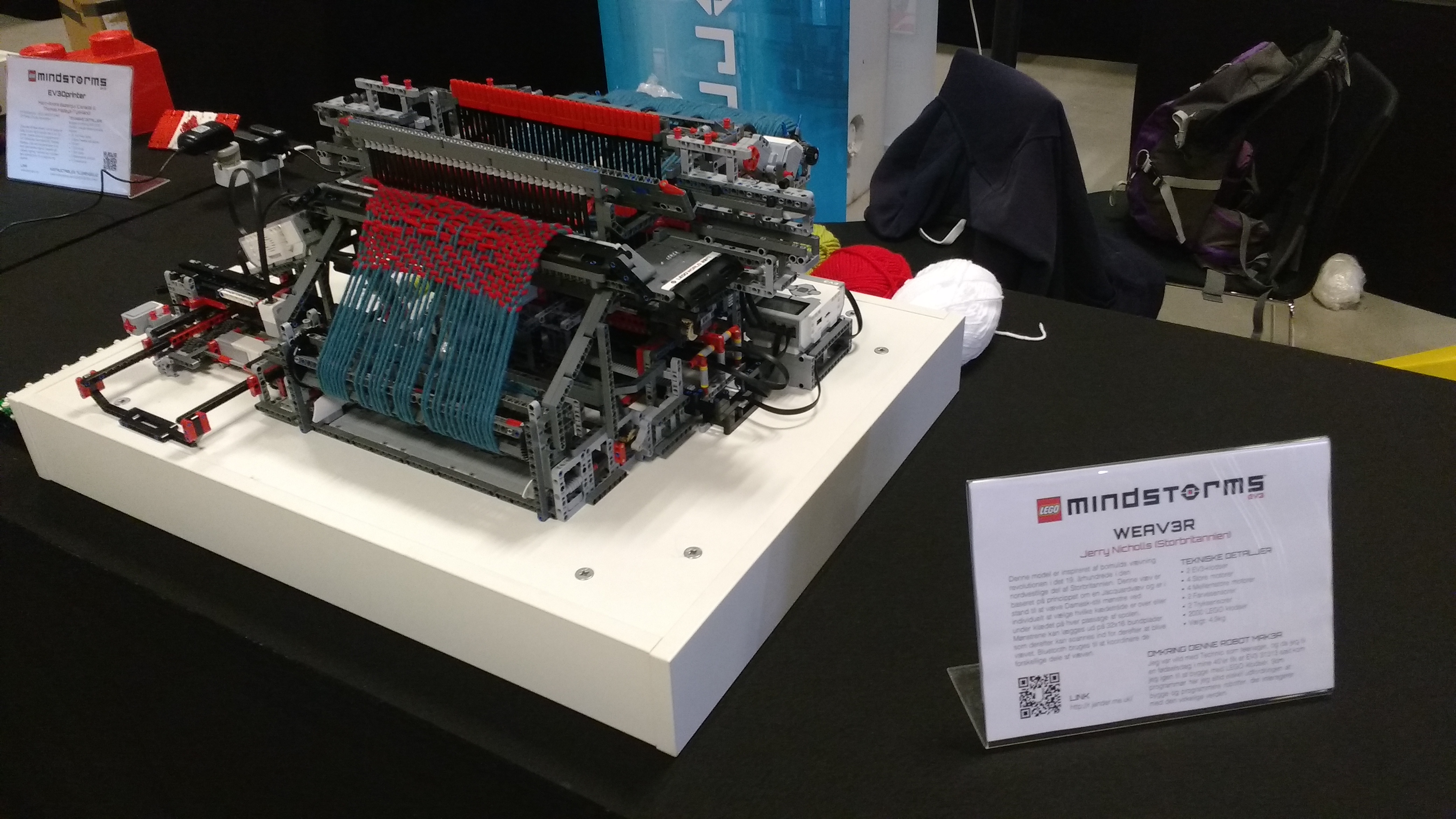
I was so glad that it worked after being transported. I had packed it with a very large amount of bubblewrap, and the only thing that had dismantled was part of the heddle selector’s gear rack. Here’s a video of it working on Day 1:
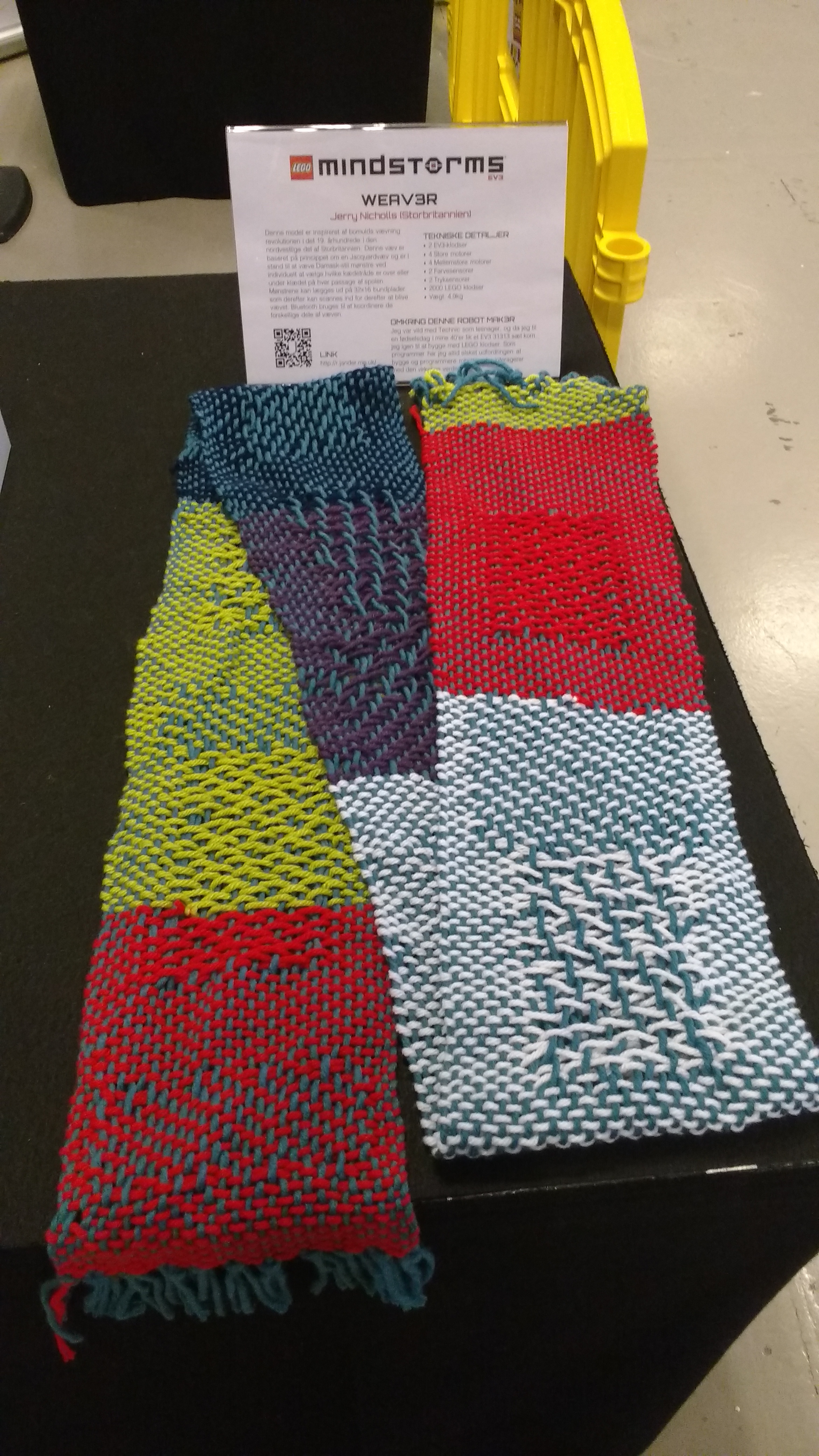
This was the first time it had actually woven anything of any length, so I was still learning how the machine would actually run. You can see in the video that the wefts are quite spread out in places. That’s due to the cloth wind-up drum running at a constant angular velocity, so as the day ran on the cloth would wind faster and faster. This lead to me altering the programming before breakfast on Day 2 🙂
The first day’s scarf.
The change to the programming allowed me to alter the angular rate of the winding reel throughout the day. This meant that as the scarf got longer I could slow it down, keeping the weft spacing in good order.
Here’s a video of it running on Day 3. This is an attempt to show how the “Jacquard” part of it works. There is a selector that can move along the 32 heddles and set a pair of pins, to the front or back, to set which ones go up or stay down. The video is not as clear as I’d like so I shall shoot another soon:
Unfortunately the loom stopped working towards the end of Day 3. It ceased to be able to align correctly, resulting in the heddle lifter arm jamming up. This happened just before the Owner of LEGO turned up:
Kjeld looking at the loom – thanks to Martyn Boogaarts for the photo.
Fortunately for me he’d seen it working a few minutes before – phew!
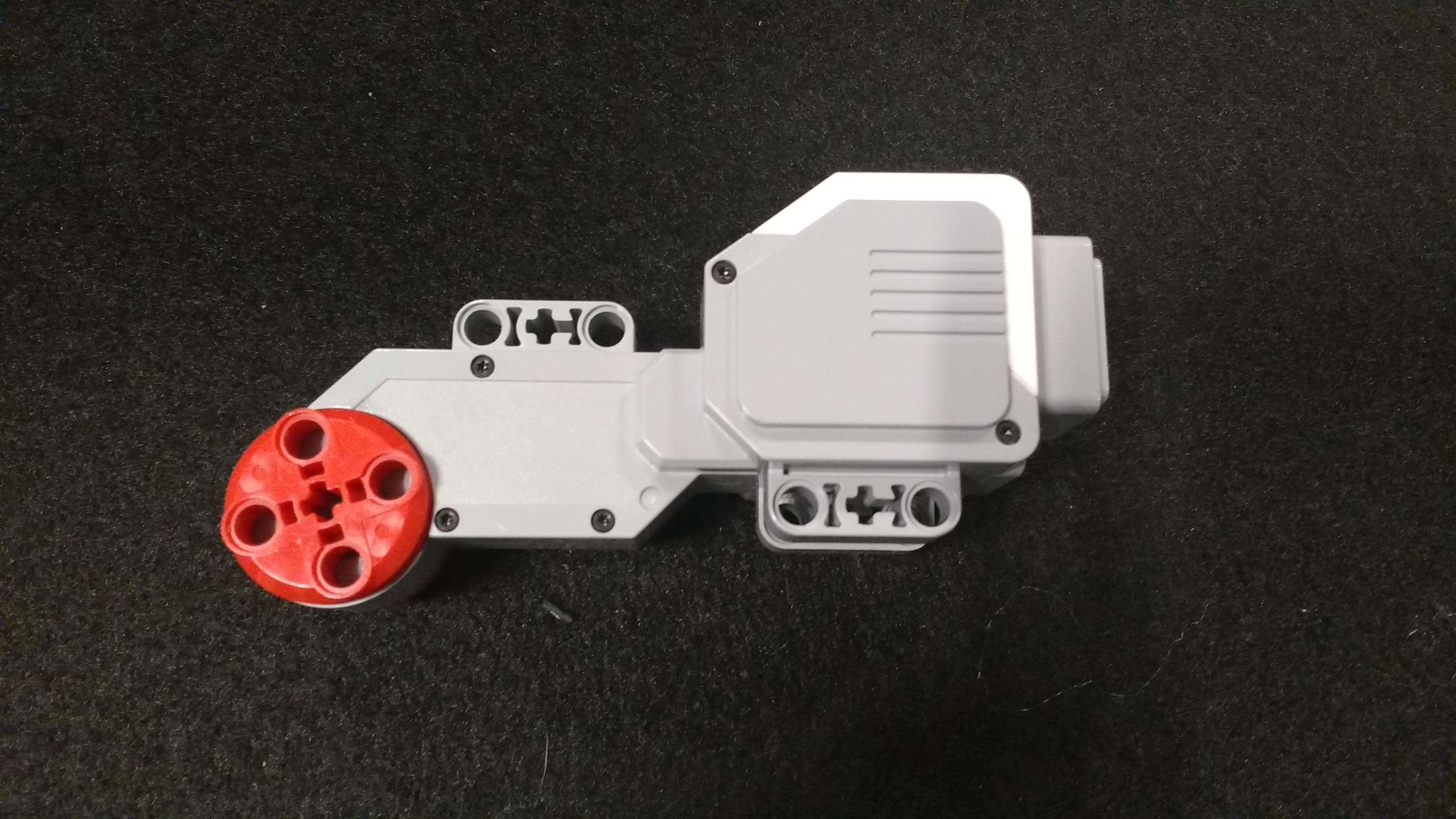
On investigation for the rest of the afternoon, and the next morning it appears that one of the motors wasn’t functioning correctly:
Wounded in Action.
On Day 4 the loom, with a new motor, it worked wonderfully. The final scarf is as below:
This was an amazing event, and taught me lots about the loom. I have several upgrades planned for the loom, but before I start on those I need to take some better pictures and video for here and YouTube.
One of the flattering things was that a few people asked if they could buy one of the scarves. Since it was the first outing of the loom I declined that – I kept the first and last of the event, and gave two to members of the MINDSTORMS booth.
In this article I will finish discussing placing treads manually using Bricksmith. In Part 2 I referred to sprockets with the notch a the top:
Notch at the top.
These are much better in terms of placing the first tread as it will sit properly in the notch as it’s on an integer grid, unlike the 90˚ rotated version which is very slightly off that grid.
Technique
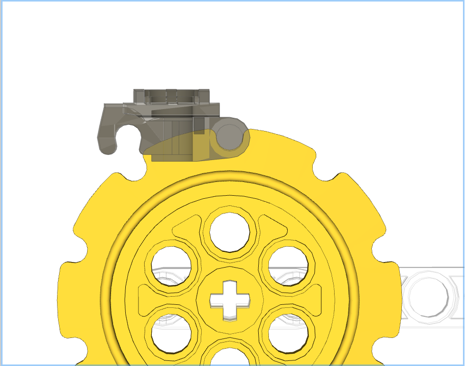
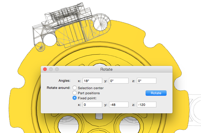
The technique is almost identical to that discussed in Part 2, but the first tread needs to be rotated by 18˚ after its initial placement:
Initial placement.First tread rotated 18˚.
A point of interest is that the tread was rotated around a Y coordinate value of -48, i.e. a radius of 48 from the centre of the sprocket. This is different to the 50 used by LSynth as discussed in my previous post about my investigations in to LSynth:
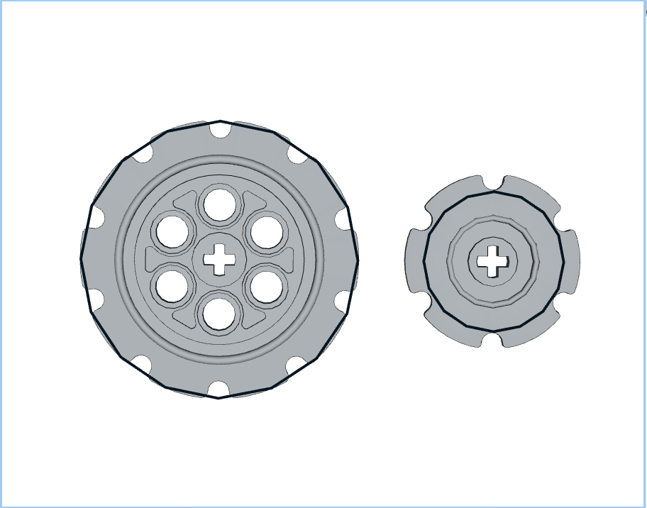
Sprocket Radii as defined by lsynth.mpd: 50 & 25.
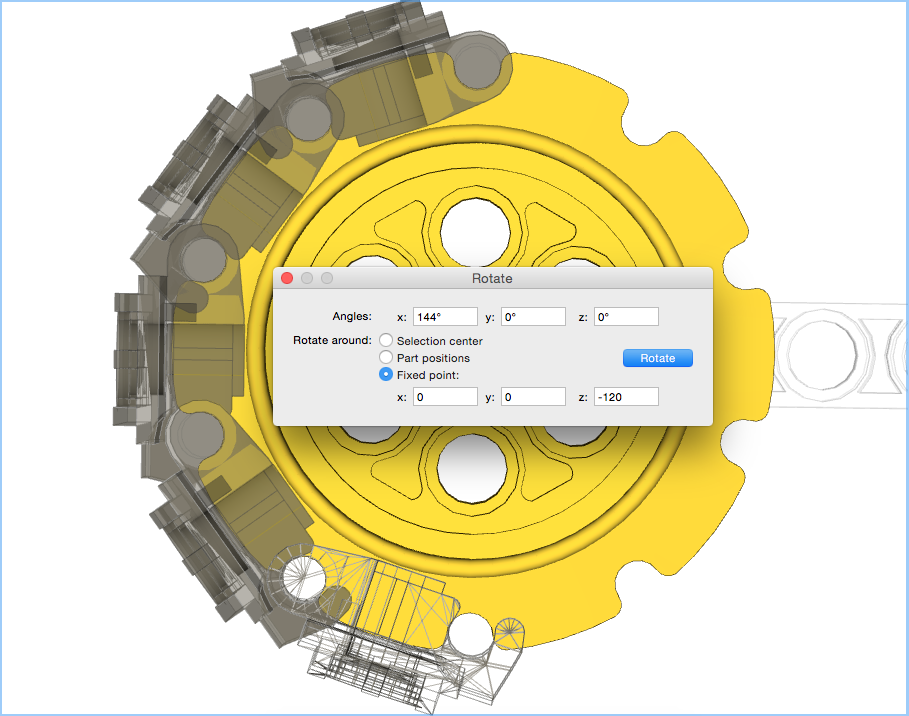
Once that first tread is in place and aligned, it is now a simple case of copying, pasting, and rotating as shown in part 2:
Second tread in place.Final tread in place.
All done. One thing to note is that treads 2-5 have undergone two rotations each, but don’t appear to suffer any level of cumulative error. This is probably due to the first tread being rotated about its origin only. This results in the treads 2-5 only having one orientation rotation, and one position translation, thus reducing the errors.
This does look a lot of effort to do manually, but I’m used to it now and find it quick enough to do, and the results look good.
After posting my “tutorial” articles on the LEGO MINDSTORMS EV3 Facebook group I started to look in to how LSynth does its magic, and now have a greater understanding of what the issue with treads is. I’ve worked through how the lsynth.mpd file works, including reading the source code. I’ll attempt to describe what I’m seeing.
Constraint Radii
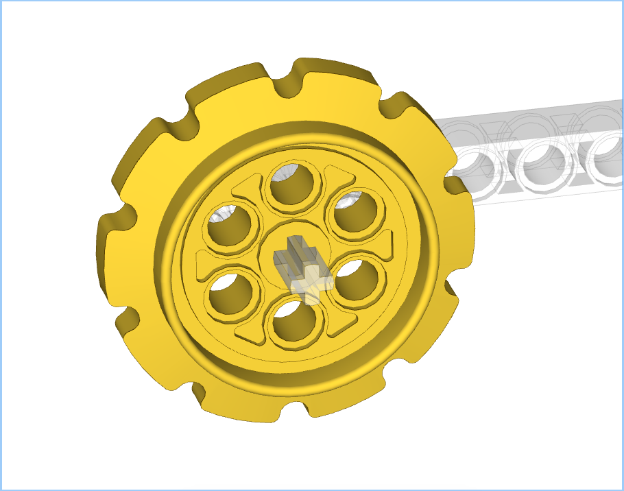
The lsynth.mpd file is used to describe the parameters around the various elements, in this case Bands, and Band Constraints. Each constraint is defined by its type, radius, orientation etc. The two sprocket types I’m interested are listed as:
This states that the small sprocket has a radius of 25 LDU, and the large 50. This is incorrect, since the large sprocket is 1.6x that of the small, not 2x. It is in fact the small sprocket that is wrong, it ought to be 32 LDU. The sizes as per the LSynth file can be seen in the image below:
Sprocket Radii as defined by lsynth.mpd.
Band Scaling
The loop of treads is defined in the lsynth.mpd file as a band of fixed size elements. Two parts are defined: one for going between, and the other for wrapping around, the constraints – i.e. the sprockets. The band definition includes a scaling value which is used for working out how many elements will be needed between constraints, i.e. the straight line segments. For the large treads this is defined as:
The scale value here is 0.03571. This should be 1/N where N is the LDU length of the segment unit, i.e. tread, in LDU. The value of 0.03571 gives N=28 LDU. This is also wrong. The distance between the centre of the hooks and pin on the treads is 30 LDU, so the scale value ought to be 0.03333. This incorrect scaling value is what leads to the “compressed links” I referred to in the previous blog. The original value, and one of 0.03333 can be seen in the image below:
Top = 0.03571 (original), Bottom = 0.03333 (corrected).
An additional benefit is that the parts around the sprocket are also now the correct number.
Numerical Accuracy
Unfortunately it appears that numerical accuracy has a noticeable influence on the appearance. With the corrected scaling value for the treads, wrapped around a single sprocket the result looks like below:
Numerical accuracy.
As can be seen, the tread pins don’t sit quite in to the sprocket’s notches. I would put this down to rounding errors.
There is another issue in the code which doesn’t actually affect things, but I will comment on it. The code works out how many treads are needed on an arc, i.e. to go around the sprocket, as the length of the arc divided by the length of the tread (as deduced from 1/scale value):
n = type->scale * 2 * pi * k->radius + 0.5;
This is making the assumption that the tread would be “bent” around the circumference of the sprocket, when in fact it is a chord between two notches. In reality this difference between arc length and chord length doesn’t have an effect.
Final Thoughts
Again, I’m not knocking LSynth – I’d be lost without it for making up cables. I just thought I’d investigate why I never seemed to get bands of treads right with it. My “fixed” lsynth.mpd file has made a difference as things are now better, but the perfectionist in me would prefer that the treads sit in the notches, so I’ll continue doing them manually.
When building up a model in Bricksmith it’s important to consider the orientation of the sprockets. You’ll want them rotated such that the treads sit in the notches correctly. Generally the sprockets are going to end up in one of two orientations, 90˚ rotation between them:
Notch at the top.Notch at the side.
The notch at the top is better as the treads will sit in the notch easily, whereas the notch at the side will require fine-grained movement to get the initial tread in place. For this particular post I will focus on the latter, i.e. notch at the side. Although this requires more initial set up the rotation of the treads is simpler. I will cover the other variant in a third post.
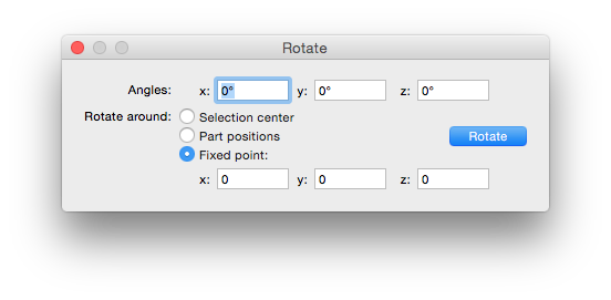
Rotation Controls
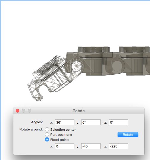
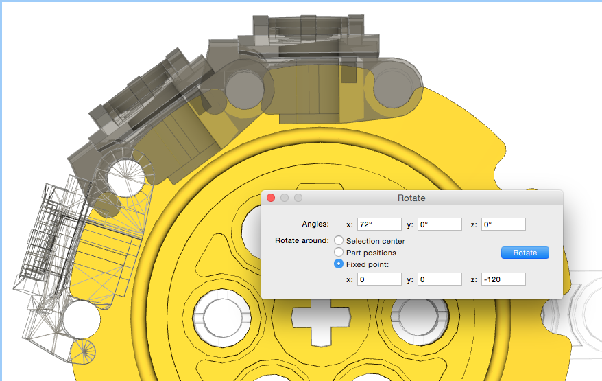
Since we’re wanting to place treads on the large sprocket, in my example, we’re going to want to rotate by 36˚. This is because there are 10 notches in the sprocket, so 360˚/10 = 36˚. The rotation controls are reachable from the Edit menu, and give a control box as below:
Edit Menu – note “Rotate…” a third of the way up.Rotation Controls.
All of our rotations will be around a fixed point.
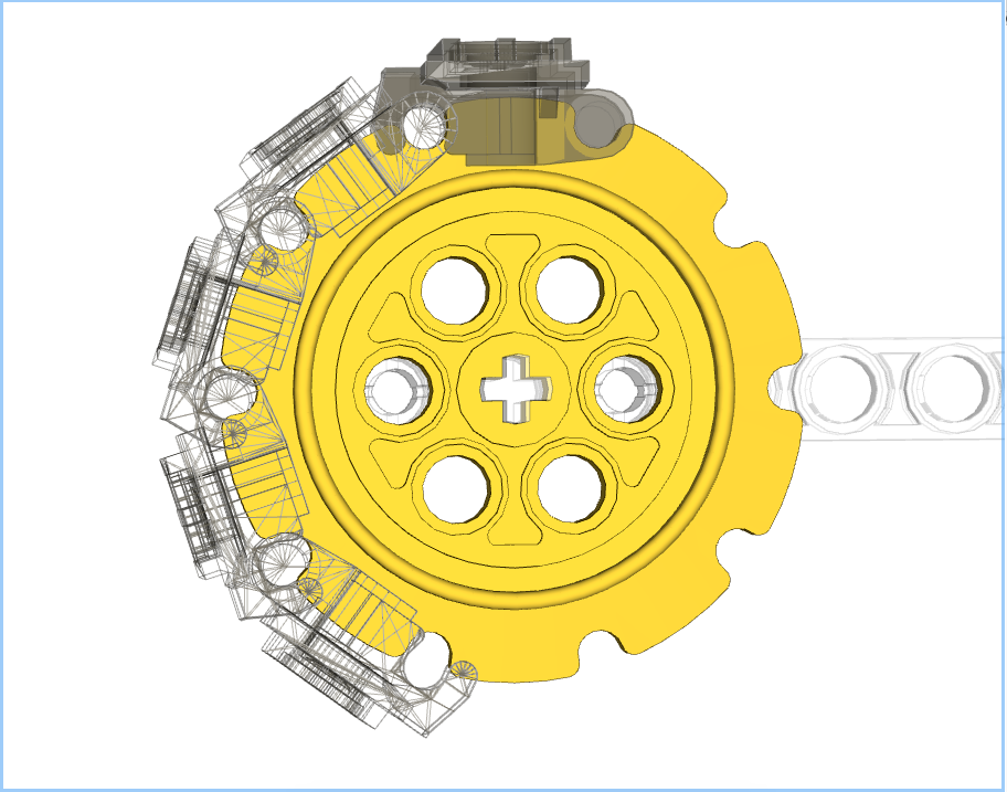
Initial Tread Placement
The first thing to do is align a single tread with the sprocket. This is relatively easy, but in this orientation will require the fine grid for movement. The first tread ought to look like:
Initial Tread Placement.
How I Used to Do Treads – aka “Introducing Cumulative Error”
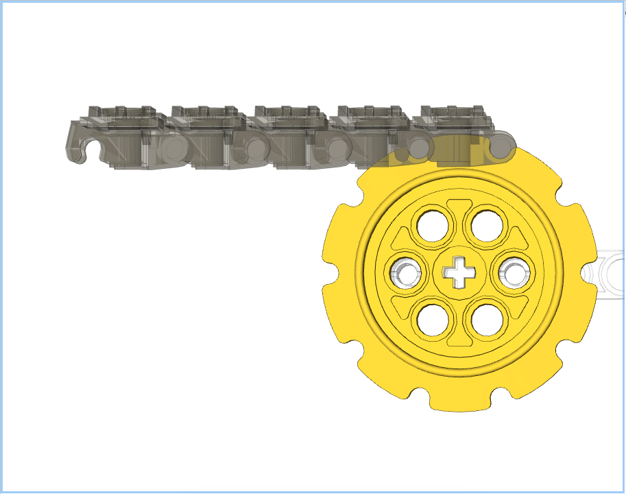
When I first started to model treads manually I’d start with a line of treads which I’d “bend” in to place:
A line of treads.
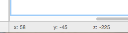
I would then select the first tread and rotate it about its pin. The coordinates of this pin can be found by moving the pointer around over the pin and observing the coordinates shown at the bottom of the Bricksmith window:
Coordinate information.
You’ll notice that two of these values change as the pointer moves but the third, in this example the x value, doesn’t. The two that change are the coordinates of the line passing through the tread’s pin.
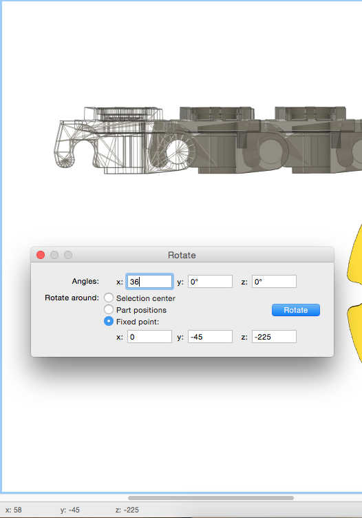
Rotation about: 0, -45, -225First tread rotated by 36˚.
Next I select the the tread I have just rotated and its neighbour. I need to rotate both of them around the second tread’s pin. I know that the pins are 30 units apart, so I already know that the coordinates will be 0,-45,-195 without needing to check:
Two treads selected.
I now simply work my way back along the treads rotating around x=0,y=-45, and z=: -165 and -135. The result of this is:
Final result of a line of treads.
This all used to make sense to me as the simplest way of doing this. However I started to notice small errors in placement. This can be seen in that the first tread doesn’t quite sit in its notches, a close up is below:
Cumulative Error.
This is due to cumulative errors appearing. The first rotation is okay, but subsequent rotations slowly add errors to the placement. This first link has undergone 4 rotations around 4 different fixed points resulting in a small drift.
Being the perfectionist I am, this wasn’t acceptable, so back to the drawing board.
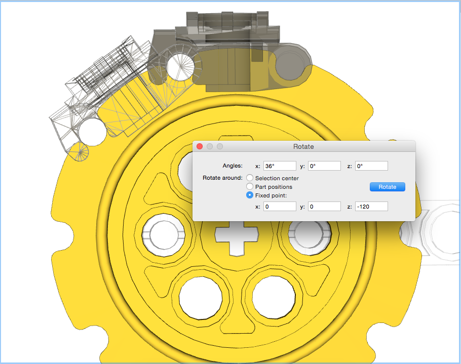
Individual Treads – aka “Doing it Right”
This time around we’ll only perform one rotation per tread, thus removing the cumulative errors. To achieve this copies of the top tread will be made, and placed in exactly the same spot, i.e. select tread, then cmd-C and cmd-V. This can just be seen in the image below with the wireframe inside the other tread:
Copy and Pasted Tread.
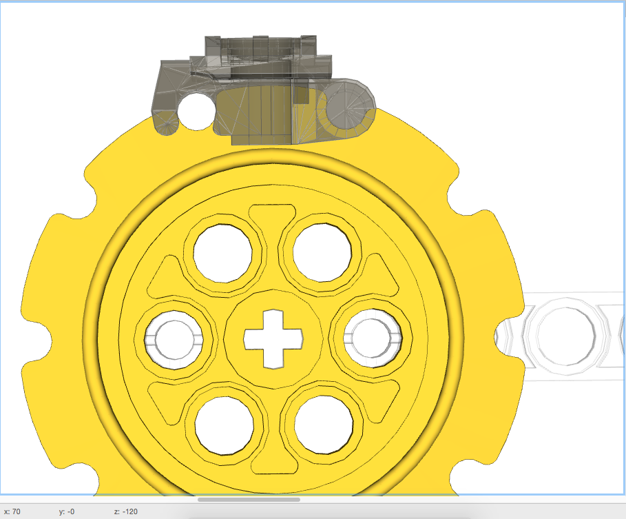
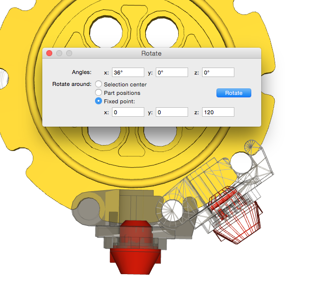
This tread will now be rotated 36˚around the centre of the sprocket, not its pin:
One rotated tread.
This will now be repeated, copying and pasting that top link, then rotating by 72˚, 108˚, and finally 144˚:
Second tread rotated.
Treads with Rubber Feet.
One of the comments I made in Part 1 was that LSynth didn’t support treads with rubber feet. To do this the first tread will need a rubber foot located with it, and then those two together can be copied and rotated as above:
Tread and Rubber Foot.Five Treads with Feet.
Completed Treads
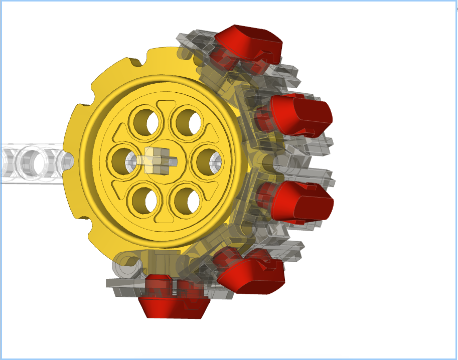
Once the sprocket treads are in place, the top/bottom treads can be placed between the sprockets. For simplicity I copy and paste the initial tread placed on the sprocket:
Completed Treads.
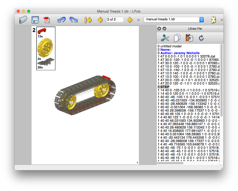
LPub4 Parts List
Another comment I made in Part 1 is that the LSynth structure doesn’t show up in the parts list. Since the treads placed via the methods above are normal elements there will be a valid parts list shown both on the page and in any Bill of Materials:
I hope this makes sense. Feel free to leave comments if I need to make anything clearer.
Bricksmith and Treads – Why they aren’t quite right.
When it comes to making my building instructions (BIs) I use Bricksmith for OSX. It’s a brilliant package for making models and even better it comes with LSynth integrated in to it. LSynth is excellent at doing flexible objects – most specifically the EV3 cables. It, however, doesn’t handle treads at all well; which is what this post is about. I’m not knocking LSynth in any way, but want to focus on how to get treads correct in Bricksmith, which unfortunately will be a manual process.
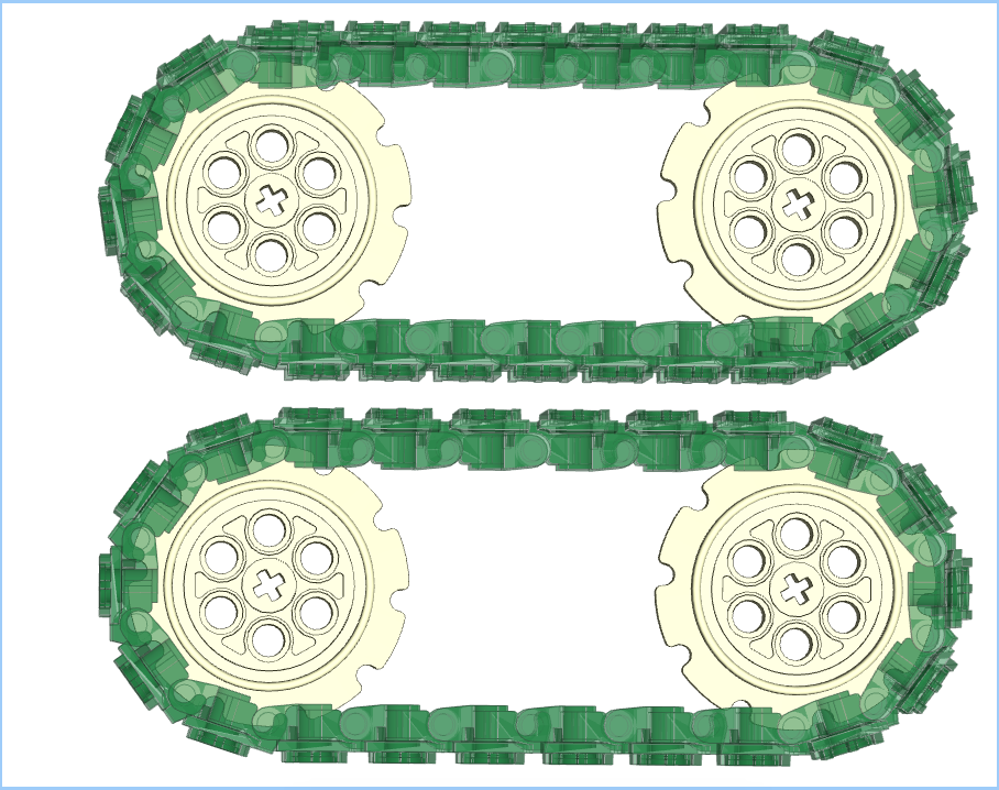
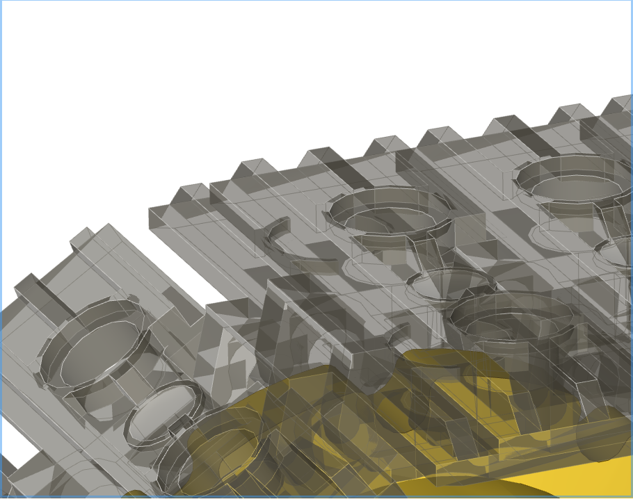
I figure that I ought to start by showing why I don’t use LSynth for my treads. Here’s a model with some treads:
This all looks good; I’ve used “trans black” and “trans clear” for parts so that we can see through them. This model ought to have 26 treads in it, however if one counts what’s in this model LSynth has put in 30 of them. This leads to the following issues:
Overlapping Treads
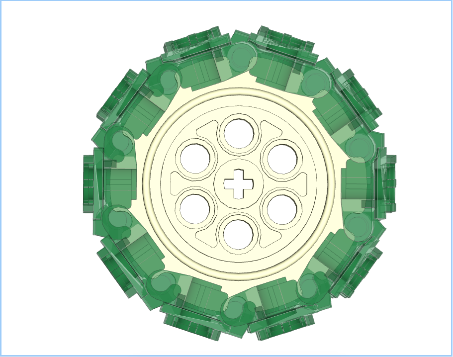
If you look at the picture below you can see that two of the treads are overlapping, and occupying most of the same space. This happens twice in the model, top left and bottom right:
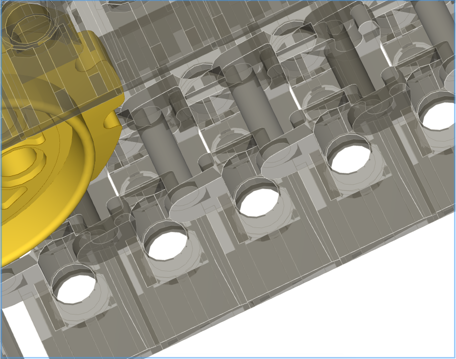
Compressed Treads
In the next picture it can be seen that the treads are far too close to each other. They are butted next to each other, but this results in the treads not joining at the pin / hooks which should be clear:
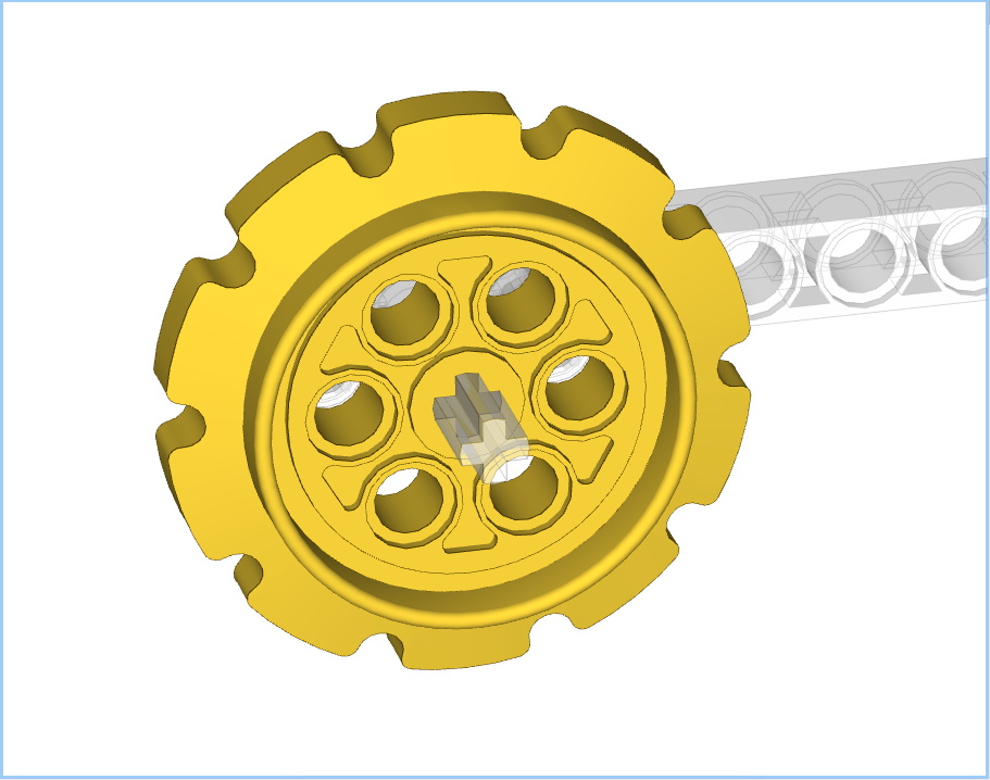
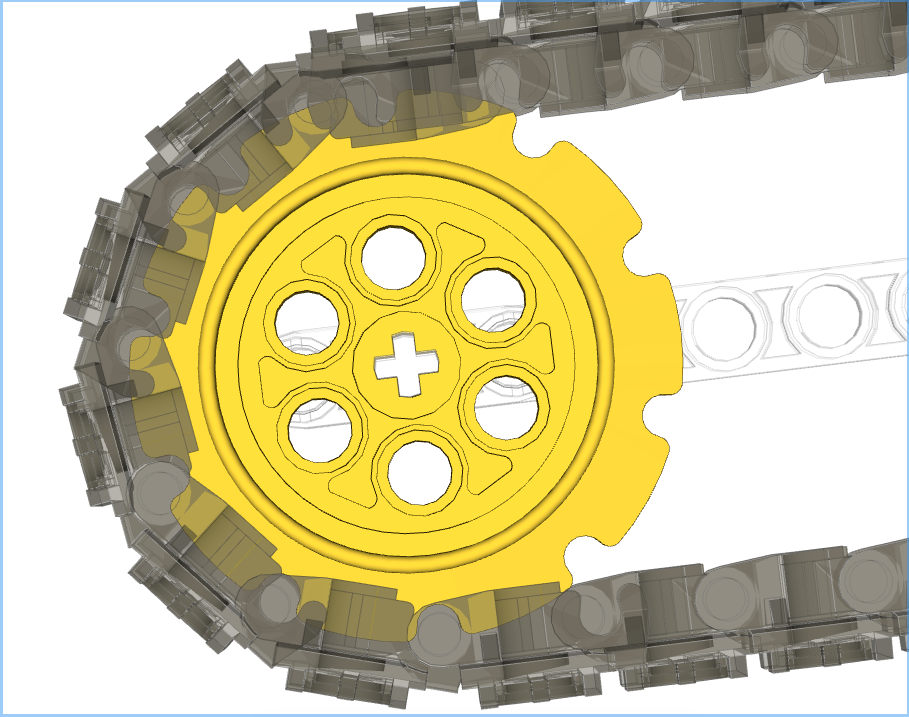
Misaligned Treads
The next picture shows that the treads don’t align with the sprocket correctly. The bottom most tread almost has its pin in the sprocket’s indent, but not quite. As the links carry on around they progressively get further and further out of alignment. This is probably related to the earlier observation about the compressed treads.
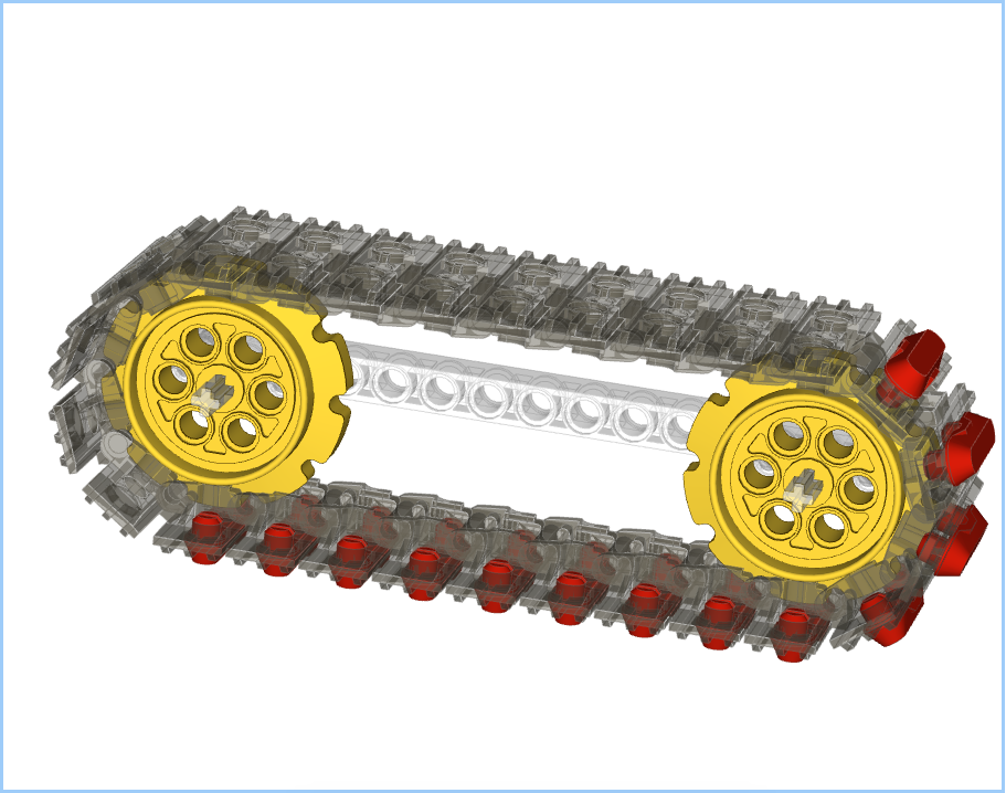
No Rubber Feet
This isn’t really an LSynth problem as such, but there is no option for a band of treads with the red rubber feet, as below:
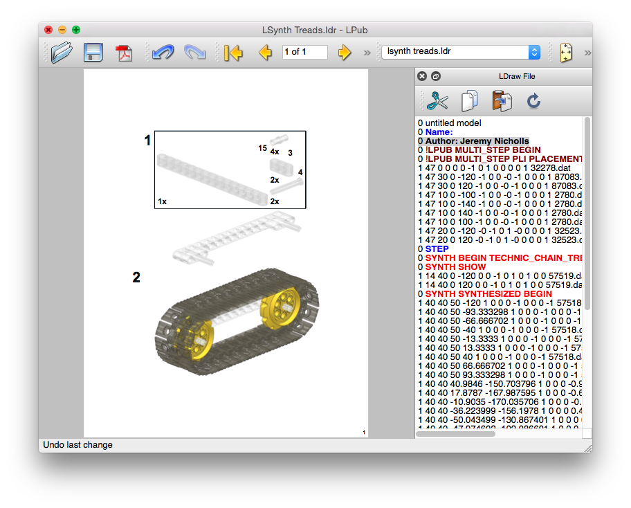
No Parts List
Again, this isn’t the fault of LSynth, but when an LSynth element is presented to LPub4 it doesn’t see it as a list of parts, so no list is shown. See the image below; there are parts for the beams and axles, but none for the sprockets or treads:
Conclusions
Again, I will state that LSynth is brilliant for EV3 cables, but from my experience it isn’t the right tool for putting treads in to BIs. I much prefer to do those manually, which I’ll cover in Part 2 of this series.
I’ll be making another blog post soon covering how to use Bricksmith and LSynth to put together EV3 cables, including coloured ends.
So, I’m currently in the process of developing my latest project: WEAV3R. This is to be a fully programmable “Jacquard” loom, i.e. apart from doing plain weave, it can do twills and, even more importantly, damask patterned weaves. Here’s a teaser of the heddles going through a twill pattern:
But, that’s not what this post is about 🙂 What I’m commenting on is the joy of redesigning a model, or part thereof, to make it right. Where I’m up to with the WEAV3R is the pattern input scanner. This is so that people can create a pattern on a 16 x 32 baseboard and for it to be woven into the cloth (well, most probably scarf as it’s only 32 warps wide). An example of a baseboard pattern is below:
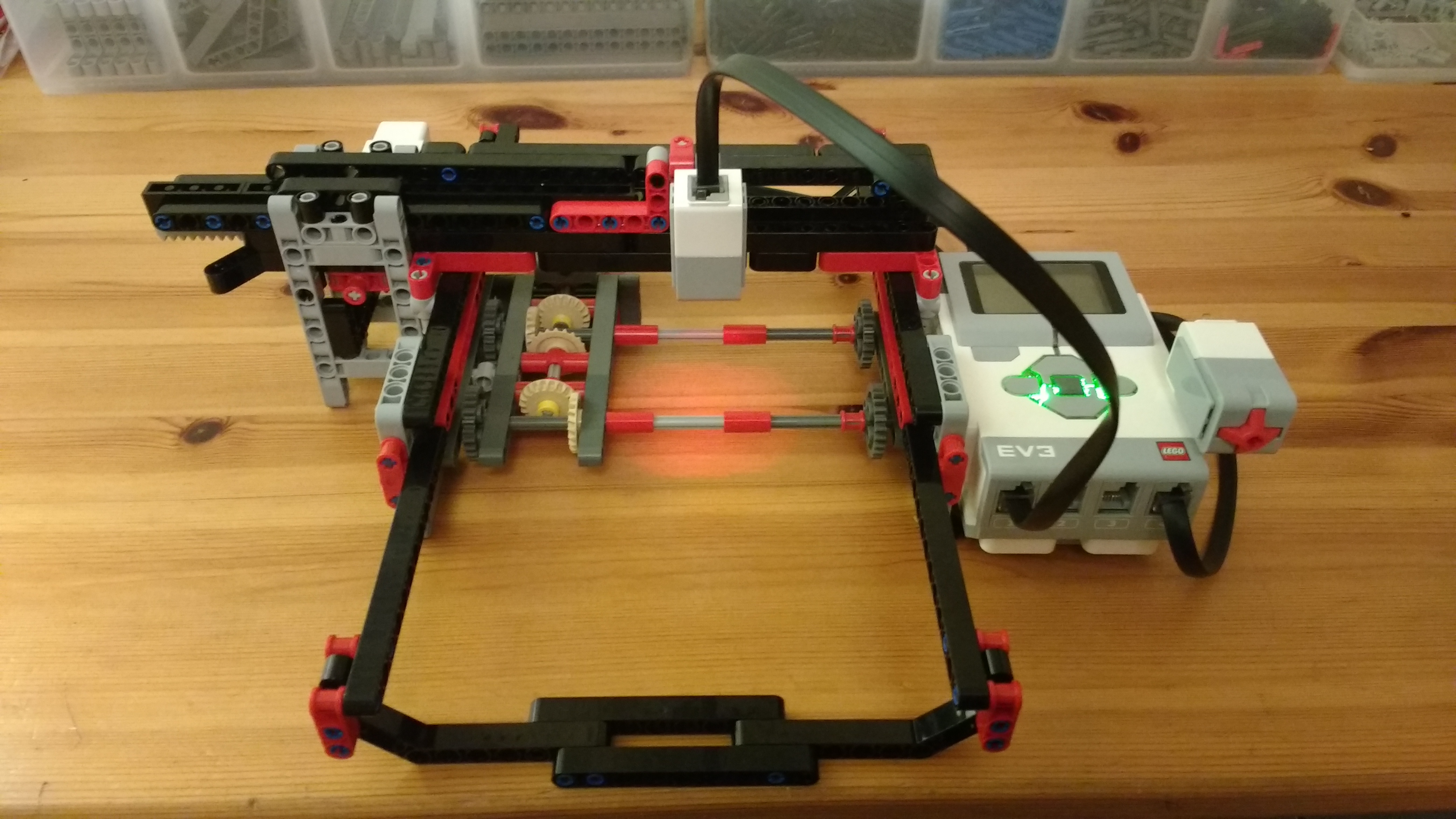
This board is then placed in a holder, and then that in to a scanner:
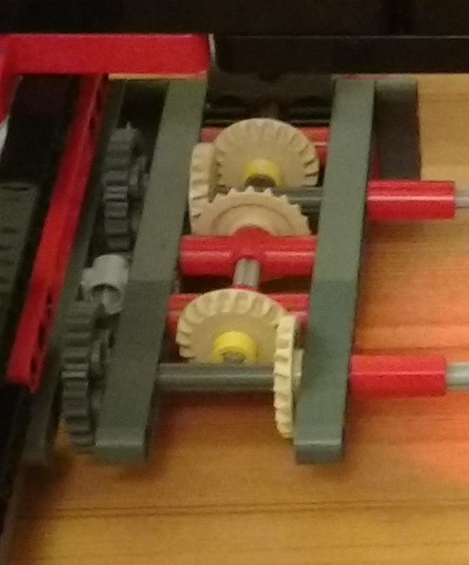
Now, I was happy with my design on the whole, but I started to see a snag/annoyance. The scanner underneath, looked like the image below, along with a zoom in on the drive gearing:
The frame that holds the baseboard for scanning has two rows of 1 x 4 racks underneath, which are driven by the pairs of 24T grey gears either side of the scanner. I use two pairs as I have a need to scan beyond the ends of the board for calibration purposes, and they both need to be driven hence the “gear box”. It’s this gearbox that started to annoy. There is a medium motor at the back driving the first of the 20T beige gears. Due to the other 20T gears in between the second 24T gear has a reasonable amount of backlash. Thus when the racks roll from one joined pair of gears to the other there is a slight mismatch in the orientation of the teeth, causing a clunk noise, and a small judder.
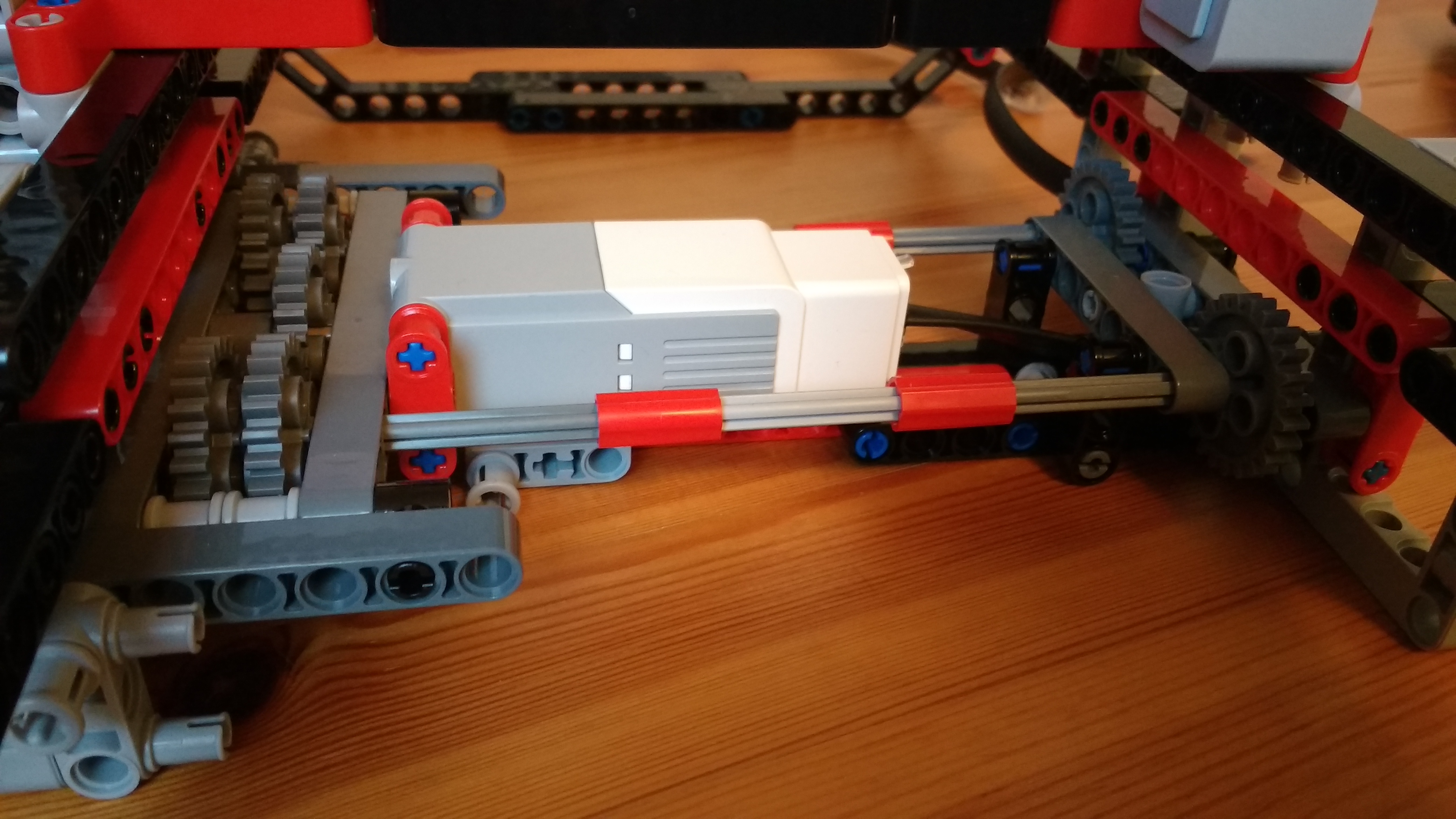
Okay, time for a redesign. Rather than use a gear box I’ll mount the medium motor between the paired gears, and drive them centrally. This has the benefit that both rack drive gears will always be in the same driven orientation. The new motor and gear arrangement is as below:
Brilliant! It’s all nice and neat, rigid enough and no mismatched backlash. That’ll work perfectly … oh no it won’t! 🙁 The scanning frame is now catching on the top of the motor – D’oh. The frame looked like below:
This shows the top view. The central frame and 45° bent lift arms are to make it more rigid. The issue I now had hit is that the frame, when sitting in its slot, is riding very slightly low due to the 7mm / 8mm beam dimensions along with a very slight droop in the lift arms due to the weight. The lift arms needed to be removed or raised up by one beam’s height. Due to the location of holes this just couldn’t happen in the space allowed. Some pondering and some tinkering this morning I came up with:
So overall the same level of rigidity without too much extra mass to worry about [It’s been slightly altered since then, but only cosmetic].
So, as usual, redesigning one section has a knock-on to other areas 🙂 This is all part of the fun of building things to me. The Jacquard selector mechanism for the loom is on revision 8 at least, as I’ve built that up and had to go back on sections. The worst of course is where one has to dismantle almost the whole thing to change a small inner part 😉 I think that happened on revisions 5-7 of the Jacquard!
Over the next couple of weeks, as I get time, I’ll get on and code the scanner up and post a video of it at work. That in itself will be an interesting challenge, especially as I want it to send the resultant scan, via Bluetooth Mailbox messages to the 2nd EV3 that’ll be driving the Jacquard.
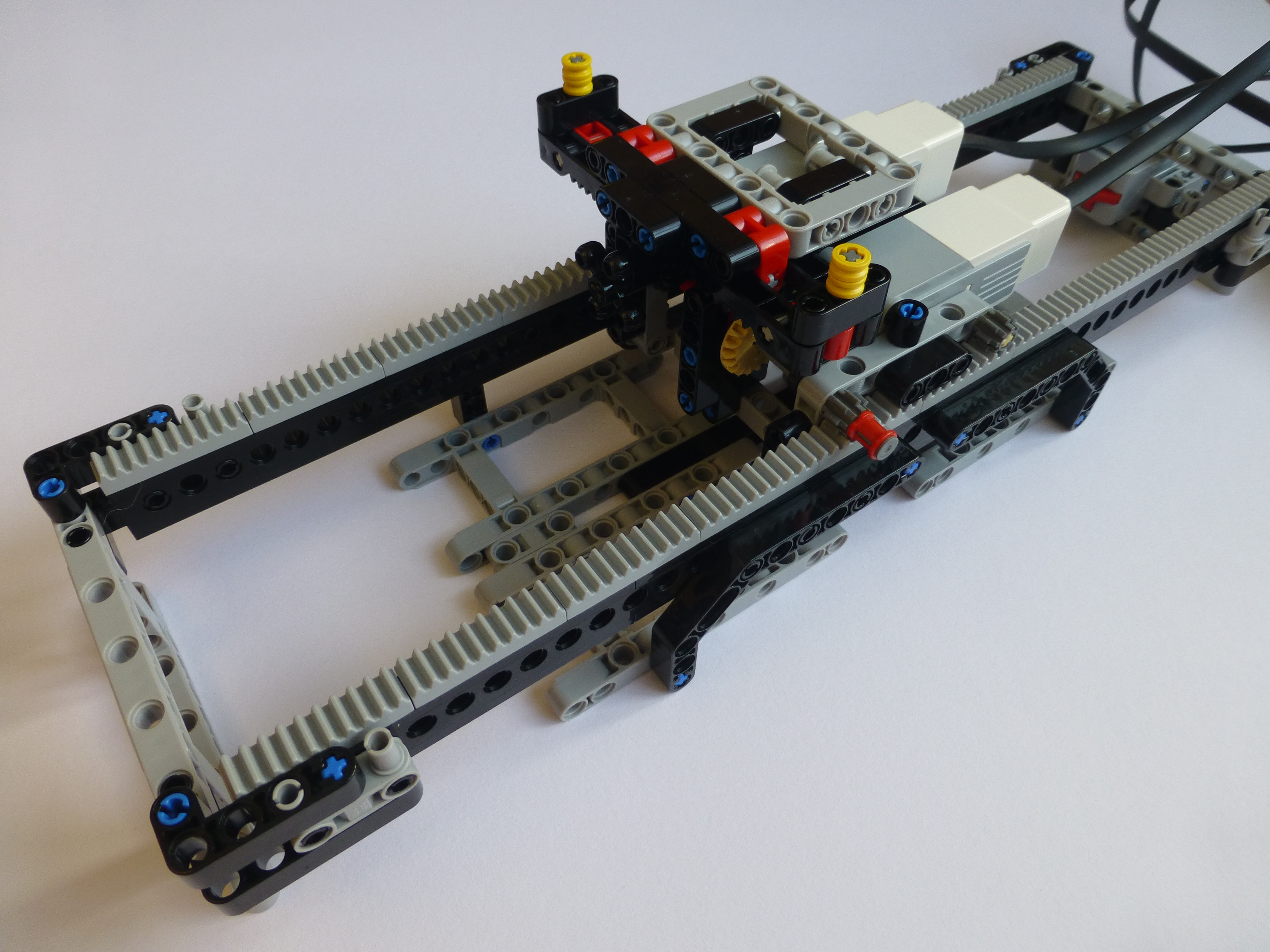
So, I’ve started work on my next project. I’ve had plans for this since around May, but haven’t had the opportunity to start on it until now – this will keep me occupied during the long Autumn/Winter evenings 🙂
I want to get a bit further with my build before I discuss what it will ultimately do, so for the moment it is codenamed “Ripl3y”. Here are a few pictures of what I have so far:
This gives me an X-Y mechanism for the core function of the project. It’s interesting using a mix of the stud-less and studded beams. It’s been quite a number of years (decades) since I’ve used studded beams, so I’d forgotten that they are essentially 1/2 a beam out of alignment with the stud-less versions. Thankfully that’s not caused me any issues. The build will ultimately have another four long linear functions that use the rack pieces, so this has been a good learning exercise.
Here’s a video of it initialising itself and going through a simple test routine to check that I’d got my degrees of rotation calculations correct:
I’ve got a lot more building, and I mean a lot more, so I’ll be posting more about it soon I hope.
So, I’ve carried on with my work on writing an AI2 app to send Mailbox messages via bluetooth to an EV3. I now have a platform I can work with for my particular needs.
Before I discuss my results, I figure it’s worth covering the path that’s lead me to this point. Back in July I was showing off my Plott3r at the Manchester Bricktastic event. One thing the children often asked was could it write their name. The answer to this was ‘no’ since there was no way of getting user-defined text in to the Plott3r (irrespective of no ‘font’ being defined). So since then I have been looking at how to do this. My options have been:
LEGO keyboard – very complex, but I’m still considering mechanisms.
“Pantograph” style pen mechanism – too much backlash in my prototypes to be accurate.
Ultrasonic triangulating system – this would work out where a stylus was over a keyboard layout. This proved too jittery and inaccurate.
Using an old mobile phone to send a text message to the EV3.
The last one of sending a text message seemed to be the simplest. Many kinds are used to using a touchscreen keyboard, so would be easiest to use. So the next challenge was to work out how write an App to send text to the EV3. After some searching and chatting I came across MIT’s App Inventor 2 which looked perfect for the job, especially as it has EV3 support for some things. So that’s what I’ve been working on.
Unfortunately for me AI2 doesn’t (yet) have support for Mailbox messages with the EV3. Since it has a SendBytes method for the bluetooth client I could look at how to send a ‘raw’ Mailbox message. Thankfully there are quite a few good resources out there; two of which I found useful are:
They had enough information in there for me to construct a simple message that I blogged about previously (My First BT Message). Since then I have expanded on that to produce a procedure that can take variable input text messages.
I’ve had to go down the path of implementing IEEE 754 so that I can send floating point numbers to the EV3. These are the reasons why:
I want to send a string of text to the EV3 to be plotted.
That text has to be sent as a Mailbox message.
EV3g, the default language, has poor text manipulation capabilities so I’d have to send one Mailbox message per-letter.
I implemented the text Mailbox method that can take any length message even though I’d only send one letter at a time – getting the Android device to do the text string manipulation.
My original concept of taking each letter and looking up, using a huge switch statement, the stroke paths needed for that letter won’t work. It’s not (apparently) possible to have a switch statement case that can match a double quote “, or a newline \n. Oh dear.
Since the app is already converting the text into ASCII values I could just send them over instead. That way I can match numerically on ASCII 10 and 34. This has the added advantage that I can then use array lookups instead – look up in one array for the offsets in to the stroke data.
I can’t just send raw byte values. The EV3 uses IEEE 754 floating point for numbers, so I have to send that in a Mailbox message.
Oh dear – AI2 doesn’t have a native IEEE 754 implementation. Oh well, let’s write my own!
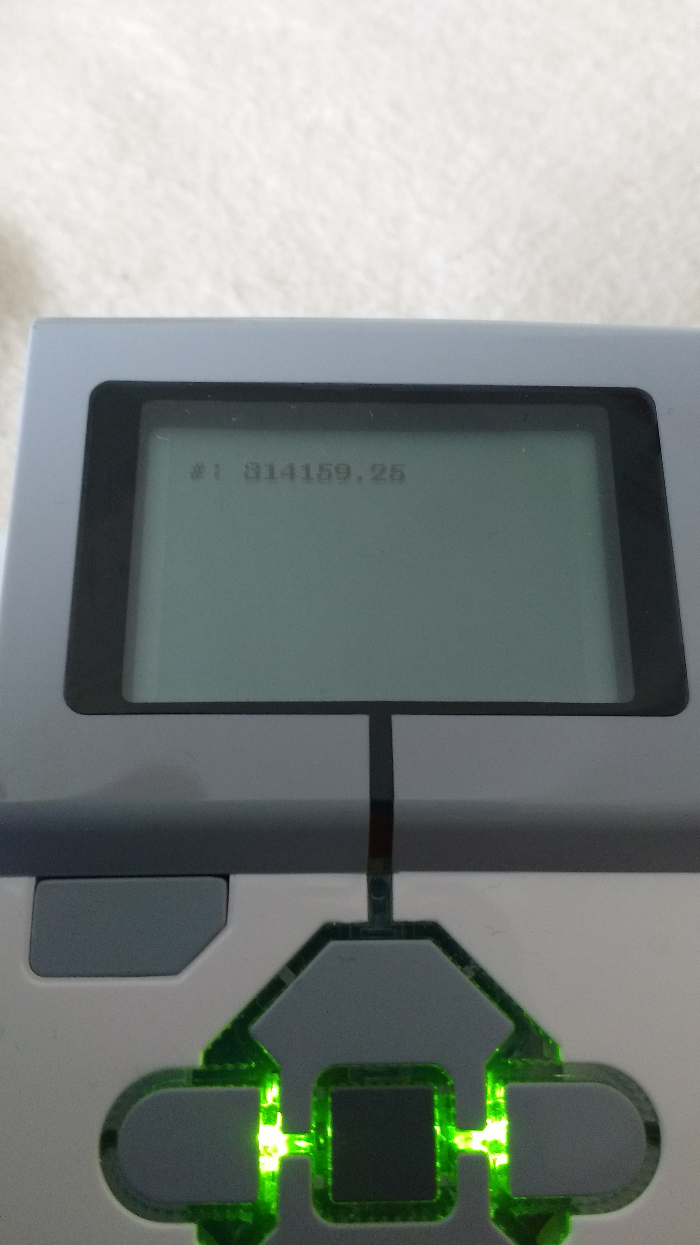
So here I am. I’ve now written an IEEE 754 implementation. It’s incomplete as it doesn’t handle underflow at all, but does do the number range that I need, zero, and NaN. I only need to send 0-255 over, but it does do most of the numbers that the EV3 will realistically need to deal with.
The value entered was 314159.26 but was sent/received as 314159.25. This is correct for a 32 bit float, and is confirmed via Perl scripts and an online converter.
I need to split the text into individual letters to send the ASCII value.
I need to program the Plott3r to accept a stream of values and special codes to plot.
I need to work out some form of ‘font’ to be plotted.
The final app needs to be written to make it easy to use.
A LEGO® ‘holster’ needs to be made to hold the phone 🙂
They’ll take a while, but I’m a good way there, I already have ideas for how to do points 1-3, especially 2-3, so we’ll see how they pan out. Updates to come.
 The PDF for the building instructions can be found at: