Ever since I started to show my LEGO® loom on this blog, Facebook and YouTube, I’ve had people ask me for build instructions. I’ve always said that I’d make them, and I will stick to that … but it’s a BIG task, and will take a long time.
Recently I’ve been making changes to the loom, so have been removing old parts and making new modules to replace them. What I decided to do as I went along was to actually model the parts I was removing, and to model the new parts as I went. This way I have the old parts for reference should I ever want to look back on them in the future, and the new parts have been modelled from the start. As time goes by I intend modelling the separate “modules” of the loom, and then build up a body of work of all the sections. I’ll still need to model the main framework of it, but that will come in time.
So, without further ado, here are the parts I’ve done so far.
Warp Thread Drum
This is the original warp thread winding drum. This was used at the back of the loom and stored the warp threads for feeding in to the loom. In my original build I used to have to wind the warp threads on, en masse, by hand. This suffered from a) being tedious, and b) the threads would wind on at different rates. Since the threads didn’t lie completely flat on top of each other, the drum would end up with different “thicknesses” of threads, resulting in some threads winding on faster than others – since C = 2πr. When the loom was running it’d pull all the threads through at the same rate. Due to the different winding thicknesses, this would either result in some threads getting very slack or, more commonly, some threads getting very very tight.
The LDraw model for this can be found at: http://jander.me.uk/LEGO/loom-parts/Warp%20Drum.ldr
Warp Thread Winding Gearbox
My solution to the differential winding of the warp drum, was to build a set of pinch rollers, that the warp threads went though, and a gearbox that drove the drum.
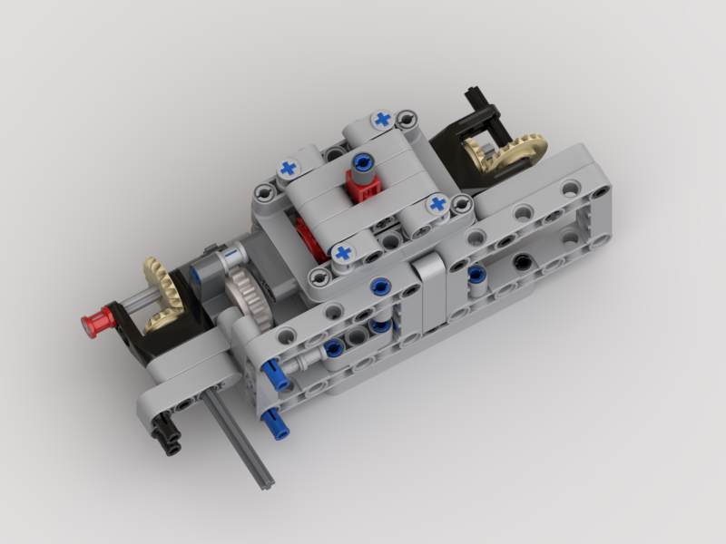
The pinch rollers would be in use during weaving, to provide a tension control between the back of the loom and the cloth take-up drum at the front. They would ensure that all the threads passed through the loom at the same speed.
The gearbox would be engaged when loading the warp drum. When engaged, the warp thread drum would rotate at a “surface speed” ever so slightly faster than the feed rate of the pinch rollers – the white clutch gear would deal with any mismatch in speeds. When weaving the gearbox would be flipped over to a gear with a friction pin, just to stop the warp drum free-spinning.
This appeared to work well, until the last time I loaded the loom. I was struggling with the threads getting caught up in the pinch rollers as they wound on. After watching it load, and thinking on it, it was the same differential speed problem as in the original loom, but in reverse. Now, as the threads wound on, they were winding on at different speeds due to not winding on flat. This was exacerbated by the use of the clutch gear. This meant that the warp drum rotated at the slowest speed, i.e. that of the thickest wound thread. The threads winding on to the thinner areas therefore became slacker, and would get caught on the pinch rollers, ultimately winding back inside them.
The LDraw model for the gearbox can be found at: http://jander.me.uk/LEGO/loom-parts/Warp%20Gearbox.ldr
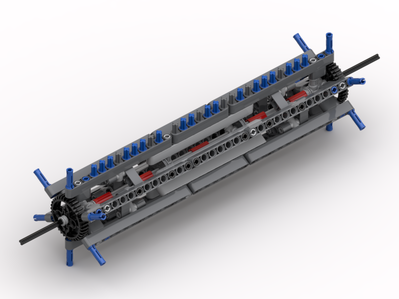
Bobbin Frame
My answer to the warp threads running at different speeds has been to make a frame that has 32 individual bobbins; one for each thread. I’ve yet to test that it actually works, but will do in the next few days. Now each thread can unwind at its own speed, and not be affected by its neighbour.
I’ve designed a frame that can hold them all, in the manner of a cartridge. This way it can be loaded up away from the loom if desired, and then clipped in to place.
Each bobbin has a black and dark grey disc, and a friction pin on one end and an axle on the other. Half of them have the friction pin on the black side, and the other half on the grey side. The friction pin is simply to stop the bobbin from free-spinning. All the bobbins will be wound in the same orientation with respect to the black/grey discs. This means that when they are all installed half will unwind clockwise, and the other half anti-clockwise. This is so that the threads don’t rub against each other (too much). The frame also has a set of long axles to act as thread separators. This is so that the threads don’t get twisted together, thus preventing them unwinding properly.
The LDraw model for the bobbin frame can be found at: http://jander.me.uk/LEGO/loom-parts/Bobbin%20Frame.ldr
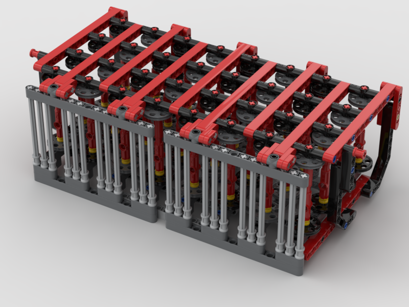
Bobbin Frame Support
To support the bobbin frame and to allow it to be easily removed and installed, a simple support structure was needed.
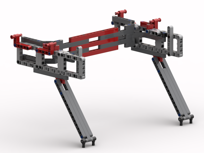
The red pin bushes at the top are used to lock the bobbin frame down on to the support. The bobbin frame itself has axle pins underneath that locate into the angled beams on top at the back. The whole thing is supported on the long angled arms, set at a 3:4:5 Pythagorean angle.
The LDraw model for the support can be found at: http://jander.me.uk/LEGO/loom-parts/Bobbin%20Frame%20Support.ldr
Bobbin Winder
Although I expect to wind the bobbins using my main winder, used for the weft threads, I wanted a winder mounted on the loom itself.
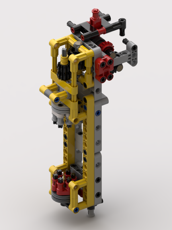
To achieve this a small winder has been made where there are two devices, dog teeth, that engage with the six holes on “wedge wheel” discs on the bobbins. The bottom one hinges out, and the top one slides up and is driven by the same motor that powers the pinch rollers. A single speed gearbox is used to engage/disengage the motor. This allows for it to be used when the loom is empty, and not powered when the loom is in operation.
The plan is to always wind bobbins with the black disc on the bottom, held by the red dog teeth. This will ensure that all the bobbins are wound in the same orientation.
The LDraw model for the support can be found at: http://jander.me.uk/LEGO/loom-parts/Bobbin%20Winder.ldr
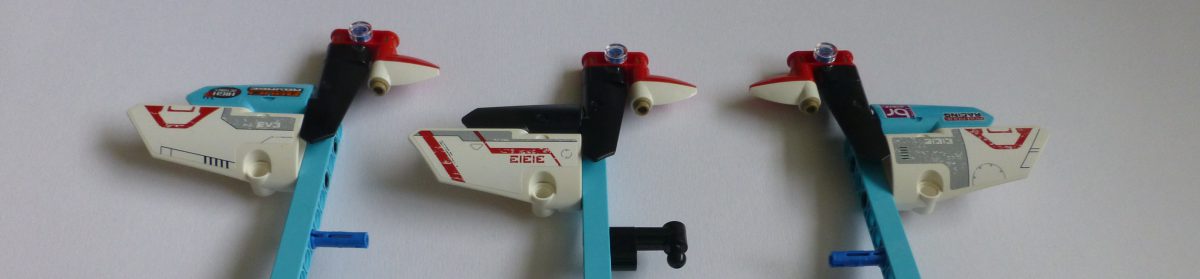
Weft Shuttle
Whilst I’ve been working on some of the issues, I thought I’d tackle the shuttle.
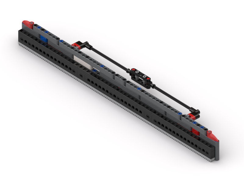
This has generally worked well, but now and again has got caught up on the threads as it’s passed through. This has been down the the “shed” (the hole inside the top and bottom warp threads being a little bit too small, and snagging the horizontal bar at the front. This bar is used to ensure that the weft comes out from the middle of the shuttle.
In my original design this bar sat 6L away from the shuttle. The supports that hold that bar in place, and the long bobbin between them, are now 5L and the bobbin sits at 2½L away. It may not make much difference; I have yet to test. If 5L is too short it is easy to modify it back to 6L.
The LDraw model for the shuttle can be found at: http://jander.me.uk/LEGO/loom-parts/Shuttle.ldr
Rendering
I build all my models in Bricksmith. I’ve used it for years, and know how to drive it. I’ve had a play with Stud.io recently, and still don’t (yet) get on with it. However, I really like the renderer that comes with it. So, I’ve been building my models in Bricksmith and using Eyesight, from Stud.io, to make the pictures seen in this article.
What’s Next?
Well, I still need to test that this all works. That’s something for this week, but I think Captain Marvel comes first 🙂