Over the past few weeks I’ve been working on a robotic bobbin winder for my Weav3r loom. Previously, at shows, I’ve had a simple motorised mechanism for winding them but it required my attention to wind. After regular suggestions from Martyn Boogaarts about making a bot to do it, I finally pulled my finger out and got on with designing one:
My intention is to ultimately release the BIs for the loom, but it is taking some time to construct the 3D models for it. One of the issues with the loom is that I’ll need to dismantle significant portions of it to find out how I built it 🙂
I mainly model things for my own benefit so should I have a need to rebuild, I can. For this model, I figured I’d actually produce a proper BI PDF and release that and the code for those that wish to have a go at building it. I should note that I have been a little lazy with the BIs and not run any cables. Instead I have inserted the cable ends and colour-coded them. You will need 1x 50cm, 1x 35cm, and 4x 25cm cables – I’ll leave the routing of them to the builder.
This model will probably need an instruction manual, although I’m hopeful that it ought to be relatively clear how it works. The video above shows how the yarn is threaded through but that ought to be obvious. The code has a menu system which also ought to be clear. If there’s enough feedback/demand for operation instructions, I’ll write up a blog article/document to do that.
Whilst we’re all in the position that we need to reduce social contact due to COVID-19, I have taken the opportunity to work on a couple of aspects about my Weav3r loom that I felt needed attention. I have definitely solved one of them and hope, when I can buy some parts, that I have solved the other.
Clicking Gears
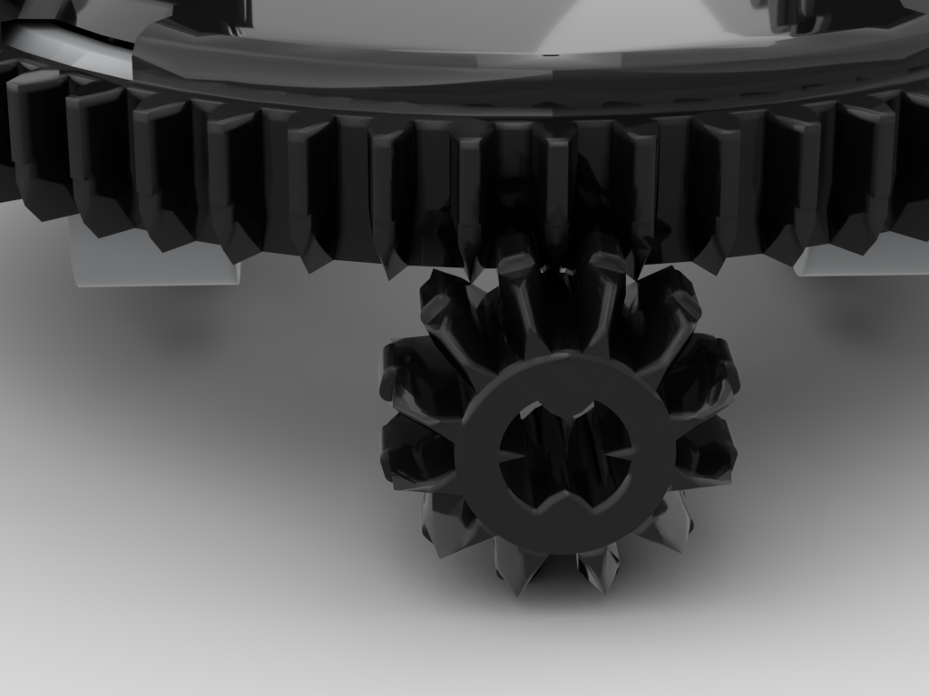
This is the problem I hope to have solved, but don’t yet have conclusive proof. Whilst working on the problem of the concentric drive I found that the mesh between the usual 12T gear and the 60T turntable was not particularly good. Looking at the image below it can be seen that the teeth of the 12T gear approach at quite a shallow angle to the 60T. This can be seen at the 11 and 1 o’clock positions – the teeth of the turntable appear to “dig in” to the 12T gear. This causes the mesh between these gears to sometimes be very rough.
When working on the concentric drive I found that the 20T gear is a much better mesh, but this requires a 1/2L offset which really just didn’t work for the loom. The other issue with using a bevel gear to drive the turntable is that the tension in the warp thread could feasibly be high enough that as the turntable rotated it would be pulled up and away from its drive gear which could also produce the same clicking problem.
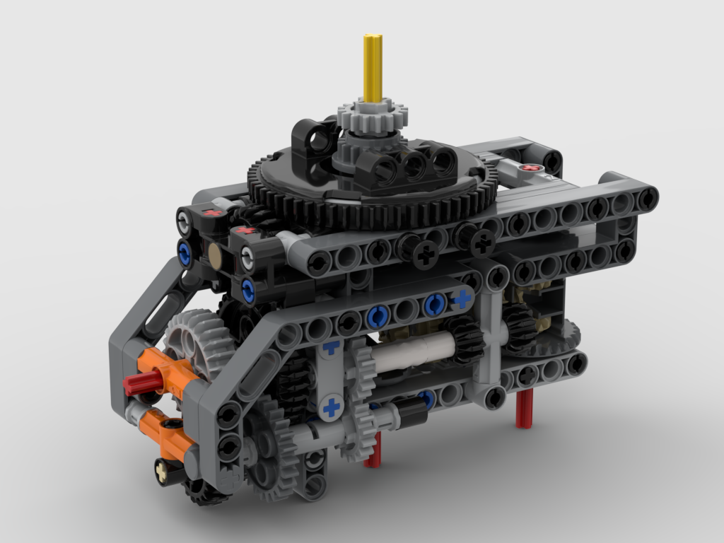
The change to the gear chain has been to have the worm gear driving the turntable. This is a great benefit as the worm drive is a much smoother mesh and, also, it is not possible for the turntable to lift off the worm. To drive the 60T turntable with a worm gear I will need to use the newer 1L type – this is the part I don’t have, but have rebuilt with the intent to use.
The existing gear chain was: 1 • 20:12 • 1:24 • 12:60 => 1:72. This used one of the old 3L worm gears, halfway down the gear chain. To use the 1L worm at the end, with the same axle paths from the large motor, the gear chain is now: 1 • 20:12 • 24:24 • 8:16 • 1:60 => 1:72, so the same ratio. However, the additional 24:24 will have reversed the direction, so I must remember to adjust my code to reflect that.
The new turntable drive now looks like the image below:
Detachable Drum
The original build’s drum was locked in to the structure. This meant that to remove the scarf, at the end of a day’s show, the whole thing had to be run in reverse for around 3m. This would take a remarkably long time, and was just extra wear and tear on the mechanism that could be avoided. So, another design criterion for this change was to make the drum removable, but at the same time retain its strong connection to the worm gear. This has, happily, been achieved.
The drum has a 5 x 7 open centred frame at each end which locks in just above the worm gear. In the image above it’s possible to see two 4L axles with stop either side and behind the worm gear. These lock in to the bottom of the drum’s end frame preventing any misalignment. The frame is locked in to place by two bush pins inserted from behind.
The drum itself has also been altered. The original was somewhat flexible and the pins along one “side” had a gap in them. The inner “hexagons” inside now have two pulley wheels inside to support them, making the drum more rigid. The structure has also been reworked to remove the gap in the pins. An added benefit to that is that there are 33 continuous pins, which equates to 32 slots between them, one per warp thread. An intermediate render, I’ve changed things a little since I made it such as the black bush pins are in the wrong place now, is shown below:
The entire front structure that encloses the drum is removable for transportation, i.e. for DHL to take it abroad 🙂 This has had some attention at the back of it, but that is more cosmetic and tidies a few things up. One humorous thing is that when I’ve detached it recently I’ve partially dismantled a section – I’d totally forgotten I’d built it so that I pull out 4 bush pins and the whole unit lowers down and forward!
Renders of the final structure with the drum installed, and removed, are shown below.
An animated render of the structure is below:
For those that may be interested, I’m posting the LDraw model. I don’t intend producing a PDF of BIs, but this model is in steps, so should be easy to follow. This work is released under the Creative Commons Attribution-NonCommercial-ShareAlike 4.0 International licence.
Over the past few days I’ve been rather nerd-sniped in to thinking about a system for passing two concentric drives through a turntable.
I’m starting to think on ideas for a bot that I plan to build later this year. This bot will need an “arm” attached to a turntable, with two motorised functions attached to it. There will be driven functions on either side of the turntable and it must be able to rotate an indefinite number of degrees, so passing cables through the turntable is not an option. This leads to the only conclusion that the two driven functions on the arm must be driven by axles passing through the middle of the turntable.
Two parallel axles don’t work, as when the turntable rotates, how does one keep the gears attached? The answer is to use concentric drive shafts. This can be done either using driving rings, or a 16T/24T empty differential. The former is no good for my bot due to the ~90° backlash in a driving ring, and thankfully I had one of the latter!
Maintaining Alignment – Unity
The next issue is what I’m mainly blogging about – when the turntable rotates, the concentric shafts need to rotate in unison. I could achieve that, to pretty good success, by driving all three motors at the same time at appropriate ratios – but where’s the fun in that? Instead I’ve opted for using two additional differentials as adder/subtractors on the input shafts for the concentric drive. So, as the turntable rotates the two differentials add/subtract a proportional amount from the other two inputs, so it all rotates together. It’s hard to describe, but it does work.
For this all to work, for each rotation of the turntable I need to have a half turn of the differentials – that results in a full rotation of the output side of the diffs. That turned out the be easier said than done. The turntable has 60 teeth, and the diffs have 28 teeth. So I needed a 60:14 ratio. Thankfully I have a SPIKE Prime, which has two of the new 28 teeth gears 😀 This works out to be: 60 *28/36 * 12/20 * 16/24 * 12/16 = 14. My resultant mechanism looks like below:
The two input shaft, red axles, at the bottom drive the two 16T gear outputs above the turntable. The red input axle on the left drives the turntable. This is as compact as I could make it.
Gearing Issues
One thing to note is the 1/2 offset 20T bevel gear that drives the turntable, as an idler gear. Normally a 12T bevel gear at normal spacing would be used. Originally I did have that but it was incredibly noisy and “crunchy”. After lots of inspection under various lights, even trying a bit of silicone lubricant I realised the issue – the 12T gear was binding up against the teeth of the 60T turntable due the the teeths’ angle of contact. As a “new” tooth from the 12T gear approaches one of the teeth on the 60T gear, the angle is too steep, resulting in the 12T gear pushing the 60T gear up rather than across. This would explain issues I’ve had with my loom clicking loudly at times – the front cloth winding roller is also a 12T/60T combination. The same must be happening there. The answer here was to use a 20T gear, but that required a 1/2 offset which was an interesting challenge to fit it, but it now works a treat.
Build Instructions
I’m a few months away from actually implementing my ideas – I have lots of things for the loom to do first – but at least I have got my nerd sniped brain over this problem. I’ve made an LDraw model of it, but haven’t got the time to turn it into full build instructions. This is being released under the Creative Commons Attribution-ShareAlike 4.0 International License and is available from:
Previously I posted an article on handling EV3g binary Mailbox messages under Python3. Since then I have carried on working on this class, along with adding a handler class.
Improved Mailbox Handling
One of the things I wasn’t so keen on with my implementation was the need to specify the type of Mailbox value, i.e. BOOL, NUMBER, or TEXT. Python’s variables have their own type, so the code has been adjusted to use the value’s own type to determine the binary payload format. It is still possible to coerce the type:
from ev3mailbox import EV3Mailbox

float_msg  = EV3Mailbox("Pi", 3.1415)

# Coerce to a string
string_msg = EV3Mailbox("Pie", 3.1415, str)
These changes have made the use of this side of the code much cleaner.
Mailbox I/O Handler
Whilst working on my use case for the original code, I had been working on the principle that I’d be using it in a simple synchronous send/receive pattern. This worked well, until I started using threads at both sides of the ev3dev <-> EV3g link. Once threads were in the mix, there’s a risk that the bt_socket.recv(…) call could actually receive a message that wasn’t destined for that particular call, but for another area of the program.
The solution to the above problem was to implement a receiving thread that deals with all the socket.recv(…) calls. Each message is decoded, and then each Mailbox name has its own FIFO of message objects. It’s a deliberate choice to maintain the list of objects, rather than just their values, so that they can be forced to floats if it’s known they may be very small – see my previous post about that problem.
The new class implements a handler that will deal with all the Bluetooth and thread side of things. All that’s then required to do is call send(…), get(…), or stop() on the class instance:
from ev3messages import EV3Messages

handler = EV3Message(bt_mac_address)

handler.send("Name", value)
msg = handler.get("ANOther")
value = msg.value

handler.stop()
The calls to send(…) and get(…) should (!) be thread safe, so calls to get(…) wait on receiving a message of the requested name.
My idea required being able to send EV3 Mailbox messages via Bluetooth between ev3dev and a stock EV3 running the EV3g language – from Python. I’m new to Python, I’m a Perl programmer at heart, so this was somewhat of a learning curve moment. I had to get to grips with Bluetooth (not that difficult as I’m used the IP networking) and Python at the same time.
I figured that one of the major selling points of Python was its extensive library of support functions, so set to looking for something providing EV3 Mailbox handling. My research wasn’t as fruitful as I’d hoped for. I could find various chunks of code but either they were flawed in their behaviour, or much more heavyweight than I wanted. So I decided to jump in feet first and write my own library.
I’d written a library for App Inventor 2 [0][1][2][3][4] that would encode & decode EV3 Mailbox payloads before, so this wasn’t too daunting a task. One aspect of Mailbox messages is that there isn’t an identifier within the payload that identifies the content: String, Float (IEE754 32 bit), Boolean. Normally this is handled in EV3g by expecting a specific type relating to the message name – i.e. a message called “status” would be defined to always be a Boolean, but “command” would always be a String – the code forces the type to remain constant. However, the type of the payload can be deduced to some extent, so I decide that I’d implement that within the Python class:
Payload length = 1 byte => Boolean
Payload length = 4 bytes
Last byte != NULL or NULL in the other bytes => Float
Otherwise => String
All other payloads => String
The only issue with the logic above is that really, really, small numbers may get decoded as strings, e.g. “@@@\x00” would get seen as a string, not 5.90052e-39 which is also a valid decode of it. As such I also implemented a .force_float() method which will re-decode the payload.
from ev3mailbox import EV3Mailbox as Mailbox

message = EV3Mailbox.encode("Name", "Message value", Mailbox.Type.TEXT)
print(message)

# Data from Bluetooth
 mailbox = EV3Mailbox.decode(payload)
 print(mailbox)
As in my previous post, I’ve been modelling parts of my loom. This update covers the two most recent.
Pinch Rollers
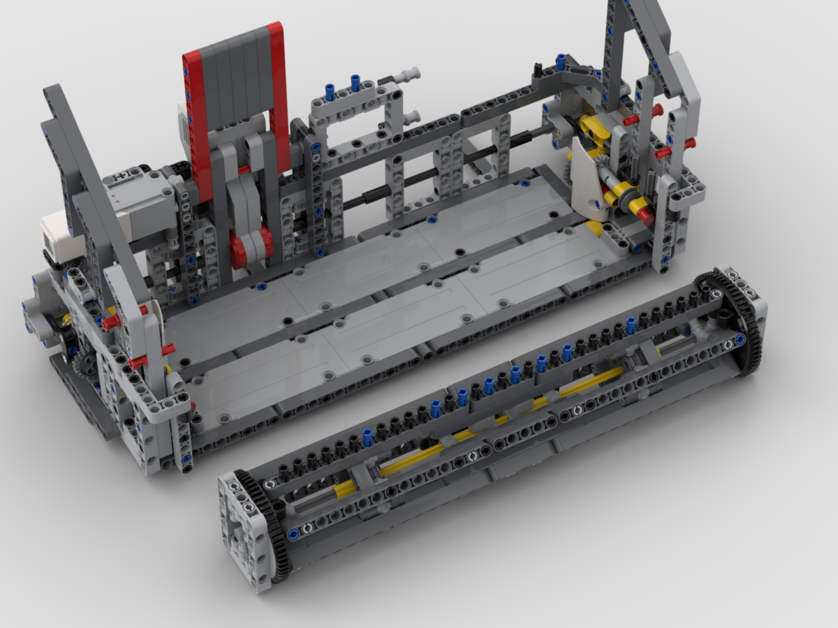
At the back of the loom there is the pinch roller mechanism. This is used to control the tension of the warp threads from the back of the loom towards the front. High tension is needed when weaving, but it prevents the lifter bar (referred to later) from lowering properly. Using the pinch rollers, the tension in the loom can be dropped by moving the warp threads forward at the back of the loom. Then when the pattern has been set and the lifter bar raised, the tension can be reintroduced by winding the cloth up at the front.
Pinch Rollers
The bobbin frame support structure, in the previous post, connects to the back of these rollers. The bobbin winder, also in the previous post connects to the lefthand side of the pinch rollers as shown.
Adding the pinch rollers, bobin frame and support, and bobbin winder all together, the over-all model now looks like:
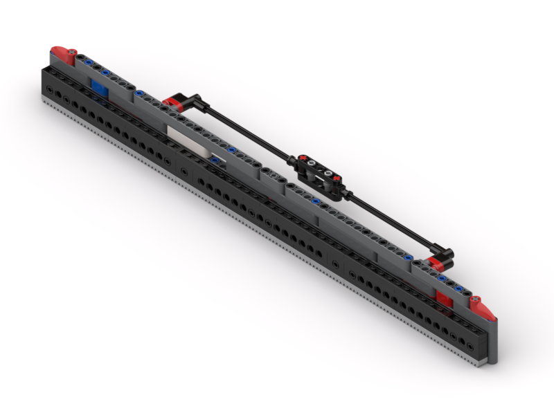
Lifter Bar
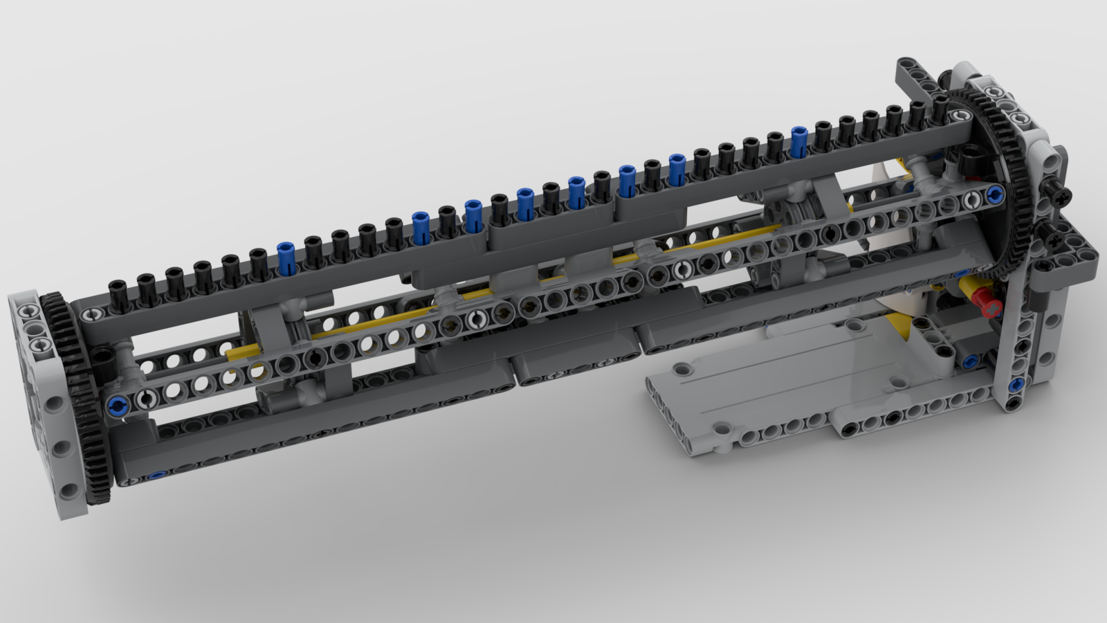
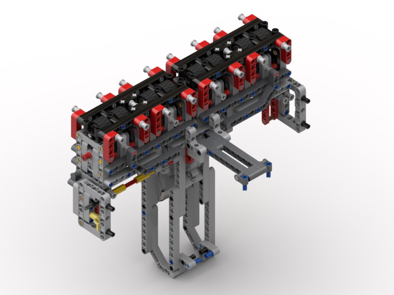
Whilst the back of the loom was off – I had to remove the pinch rollers to work out how I’d built them originally – I decided I’d model one of the most important parts of the loom, since it was visible. This is the lifter bar. It is one half of the mechanism that provides the Jacquard ability. It has 32 pins in it, that when one is engaged into the bottom eyelet of a heddle allows that one to be lifted up. There is an equivalent static bar at the front which holds the heddles down if needed.
Lifter Bar
This mechanism slides up and down along some long axles. These pass through the holes in the ends of the bars, and through some of the holes in the frames. There are gear racks at the back and sides which provide the lifting force. The lifting mechanism has to be offset away from the pins as the pin setting mechanism rides along underneath the whole Jacquard structure.
Well, I’m going to put the loom back together, and check that all my new parts actually do what I wanted them to. It’s still loaded with wool from the Mytholmroyd show at the end of January, so I’m going to run that through and then empty the loom.
I’ve then got a little bit of coding to do, to support the bobbin winder – i.e. change the direction of the motor. There’s no need to use the pinch rollers to wind the warp threads on to a drum anymore, so I can repurpose that function to the winder.
I’ve got some other things I need to focus on, and this 3D modelling is quite intensive, so I’m going to take a break from that, and will look to model some more parts in a few weeks time.
Ever since I started to show my LEGO® loom on this blog, Facebook and YouTube, I’ve had people ask me for build instructions. I’ve always said that I’d make them, and I will stick to that … but it’s a BIG task, and will take a long time.
Recently I’ve been making changes to the loom, so have been removing old parts and making new modules to replace them. What I decided to do as I went along was to actually model the parts I was removing, and to model the new parts as I went. This way I have the old parts for reference should I ever want to look back on them in the future, and the new parts have been modelled from the start. As time goes by I intend modelling the separate “modules” of the loom, and then build up a body of work of all the sections. I’ll still need to model the main framework of it, but that will come in time.
So, without further ado, here are the parts I’ve done so far.
Warp Thread Drum
3D render of the old warp drum
This is the original warp thread winding drum. This was used at the back of the loom and stored the warp threads for feeding in to the loom. In my original build I used to have to wind the warp threads on, en masse, by hand. This suffered from a) being tedious, and b) the threads would wind on at different rates. Since the threads didn’t lie completely flat on top of each other, the drum would end up with different “thicknesses” of threads, resulting in some threads winding on faster than others – since C = 2πr. When the loom was running it’d pull all the threads through at the same rate. Due to the different winding thicknesses, this would either result in some threads getting very slack or, more commonly, some threads getting very very tight.
My solution to the differential winding of the warp drum, was to build a set of pinch rollers, that the warp threads went though, and a gearbox that drove the drum.
One of two gearboxes – one either side of the loom to drive the warp thread drum.
The pinch rollers would be in use during weaving, to provide a tension control between the back of the loom and the cloth take-up drum at the front. They would ensure that all the threads passed through the loom at the same speed.
The gearbox would be engaged when loading the warp drum. When engaged, the warp thread drum would rotate at a “surface speed” ever so slightly faster than the feed rate of the pinch rollers – the white clutch gear would deal with any mismatch in speeds. When weaving the gearbox would be flipped over to a gear with a friction pin, just to stop the warp drum free-spinning.
This appeared to work well, until the last time I loaded the loom. I was struggling with the threads getting caught up in the pinch rollers as they wound on. After watching it load, and thinking on it, it was the same differential speed problem as in the original loom, but in reverse. Now, as the threads wound on, they were winding on at different speeds due to not winding on flat. This was exacerbated by the use of the clutch gear. This meant that the warp drum rotated at the slowest speed, i.e. that of the thickest wound thread. The threads winding on to the thinner areas therefore became slacker, and would get caught on the pinch rollers, ultimately winding back inside them.
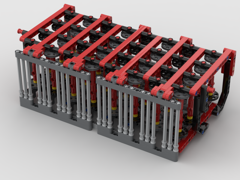
My answer to the warp threads running at different speeds has been to make a frame that has 32 individual bobbins; one for each thread. I’ve yet to test that it actually works, but will do in the next few days. Now each thread can unwind at its own speed, and not be affected by its neighbour.
I’ve designed a frame that can hold them all, in the manner of a cartridge. This way it can be loaded up away from the loom if desired, and then clipped in to place.
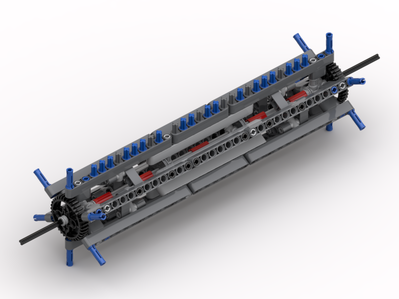
Bobbin frame
Each bobbin has a black and dark grey disc, and a friction pin on one end and an axle on the other. Half of them have the friction pin on the black side, and the other half on the grey side. The friction pin is simply to stop the bobbin from free-spinning. All the bobbins will be wound in the same orientation with respect to the black/grey discs. This means that when they are all installed half will unwind clockwise, and the other half anti-clockwise. This is so that the threads don’t rub against each other (too much). The frame also has a set of long axles to act as thread separators. This is so that the threads don’t get twisted together, thus preventing them unwinding properly.
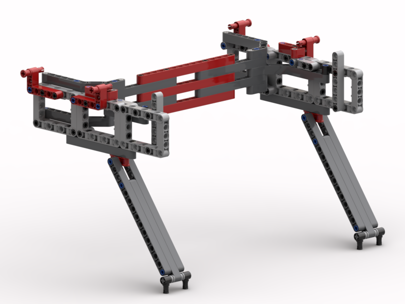
To support the bobbin frame and to allow it to be easily removed and installed, a simple support structure was needed.
Support frame
The red pin bushes at the top are used to lock the bobbin frame down on to the support. The bobbin frame itself has axle pins underneath that locate into the angled beams on top at the back. The whole thing is supported on the long angled arms, set at a 3:4:5 Pythagorean angle.
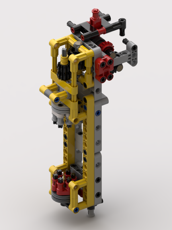
Although I expect to wind the bobbins using my main winder, used for the weft threads, I wanted a winder mounted on the loom itself.
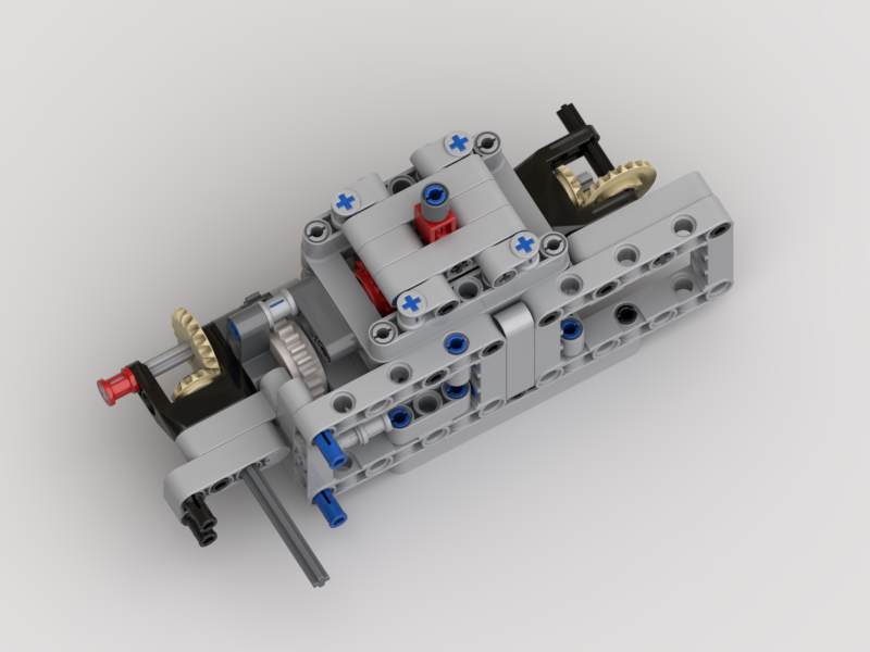
Bobbin winder
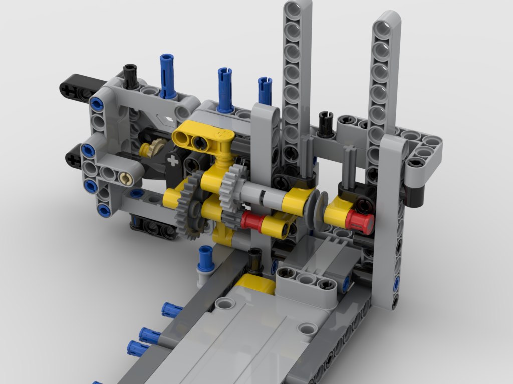
To achieve this a small winder has been made where there are two devices, dog teeth, that engage with the six holes on “wedge wheel” discs on the bobbins. The bottom one hinges out, and the top one slides up and is driven by the same motor that powers the pinch rollers. A single speed gearbox is used to engage/disengage the motor. This allows for it to be used when the loom is empty, and not powered when the loom is in operation.
The plan is to always wind bobbins with the black disc on the bottom, held by the red dog teeth. This will ensure that all the bobbins are wound in the same orientation.
Whilst I’ve been working on some of the issues, I thought I’d tackle the shuttle.
Weft shuttle
This has generally worked well, but now and again has got caught up on the threads as it’s passed through. This has been down the the “shed” (the hole inside the top and bottom warp threads being a little bit too small, and snagging the horizontal bar at the front. This bar is used to ensure that the weft comes out from the middle of the shuttle.
In my original design this bar sat 6L away from the shuttle. The supports that hold that bar in place, and the long bobbin between them, are now 5L and the bobbin sits at 2½L away. It may not make much difference; I have yet to test. If 5L is too short it is easy to modify it back to 6L.
I build all my models in Bricksmith. I’ve used it for years, and know how to drive it. I’ve had a play with Stud.io recently, and still don’t (yet) get on with it. However, I really like the renderer that comes with it. So, I’ve been building my models in Bricksmith and using Eyesight, from Stud.io, to make the pictures seen in this article.
What’s Next?
Well, I still need to test that this all works. That’s something for this week, but I think Captain Marvel comes first 🙂
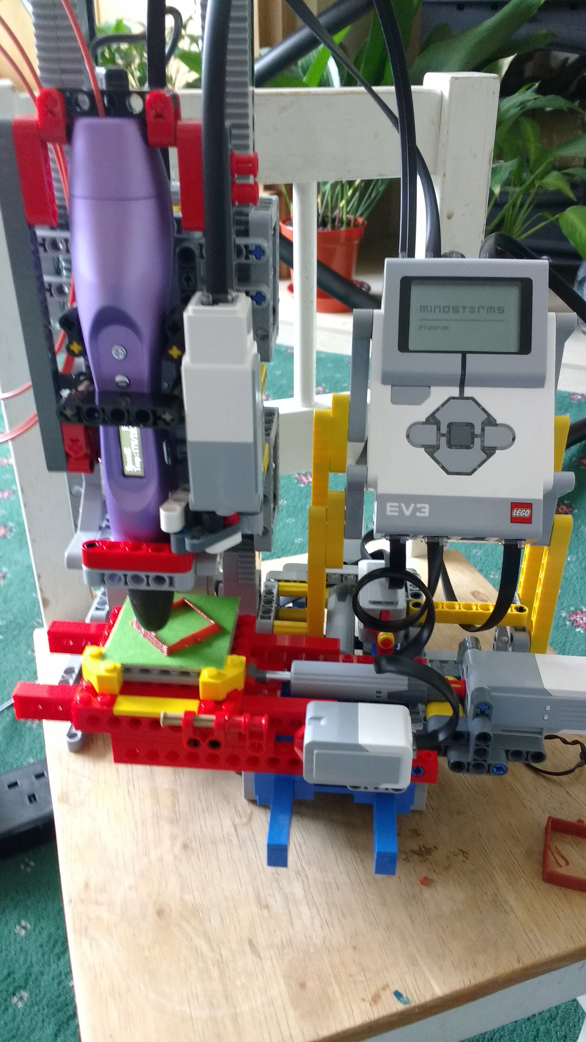
I was rather impressed by Baz’s 3D LEGO printer when I got to see it at LW2017. So, I figured that when I had time I’d build it and have a go at coding it myself. I finally got all the parts this month and have built it up – albeit in different colours, and with a few minor structural changes.
Today I got the code working for the first time! It’s not fully fledged, but it’s functional, so I’m going to post a link to what I have so that people can follow my progress. The link below points to this basic code:
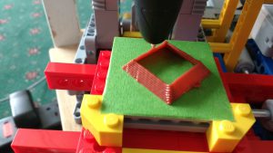
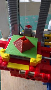
It will be expanded to do more things, such as simple geometric shapes/prisms/cones, and reading datafiles to print more complex structures. I doubt I’ll pursue the G-code system as that’s too complex to handle in EV3G.
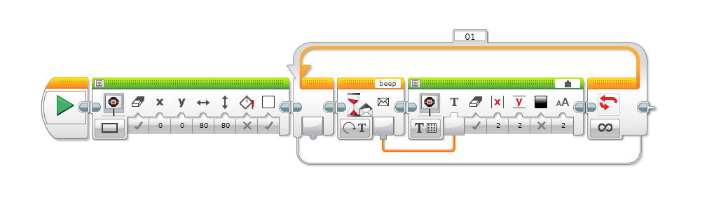
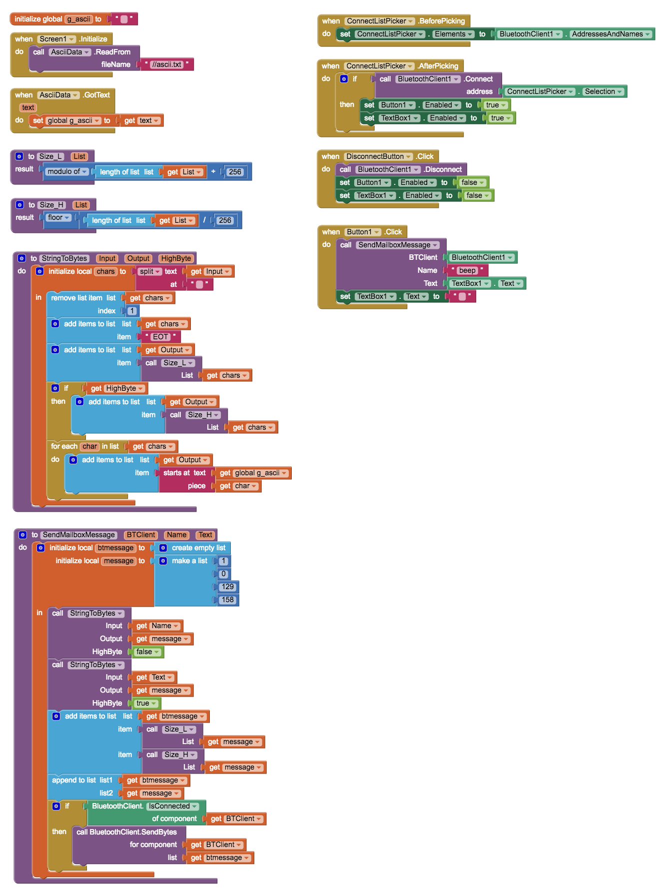
I managed to focus some more time on tidying up my AI2 app for sending Mailbox messages via Bluetooth from my Android phone to an EV3. The EV3 code is really simple and looks like this:
The AI2 code provides two BT related buttons, Connect & Disconnect, a text box and a Go button to send the text:
When the text is entered and Go pressed it is sent as a Mailbox message with the name “beep” to the EV3, and displayed on its screen. The code to send it has to construct a message in the form: