I thought I’d put all the parts that I’ve done so far together, and animate it rotating in Studio. Here’s the video:
More Loom Models
As in my previous post, I’ve been modelling parts of my loom. This update covers the two most recent.
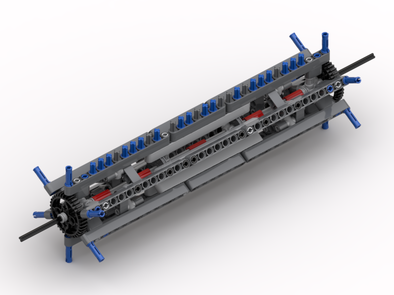
Pinch Rollers
At the back of the loom there is the pinch roller mechanism. This is used to control the tension of the warp threads from the back of the loom towards the front. High tension is needed when weaving, but it prevents the lifter bar (referred to later) from lowering properly. Using the pinch rollers, the tension in the loom can be dropped by moving the warp threads forward at the back of the loom. Then when the pattern has been set and the lifter bar raised, the tension can be reintroduced by winding the cloth up at the front.
The bobbin frame support structure, in the previous post, connects to the back of these rollers. The bobbin winder, also in the previous post connects to the lefthand side of the pinch rollers as shown.
The LDraw model for this can be found at: http://jander.me.uk/LEGO/loom-parts/Pinch%20Rollers.ldr
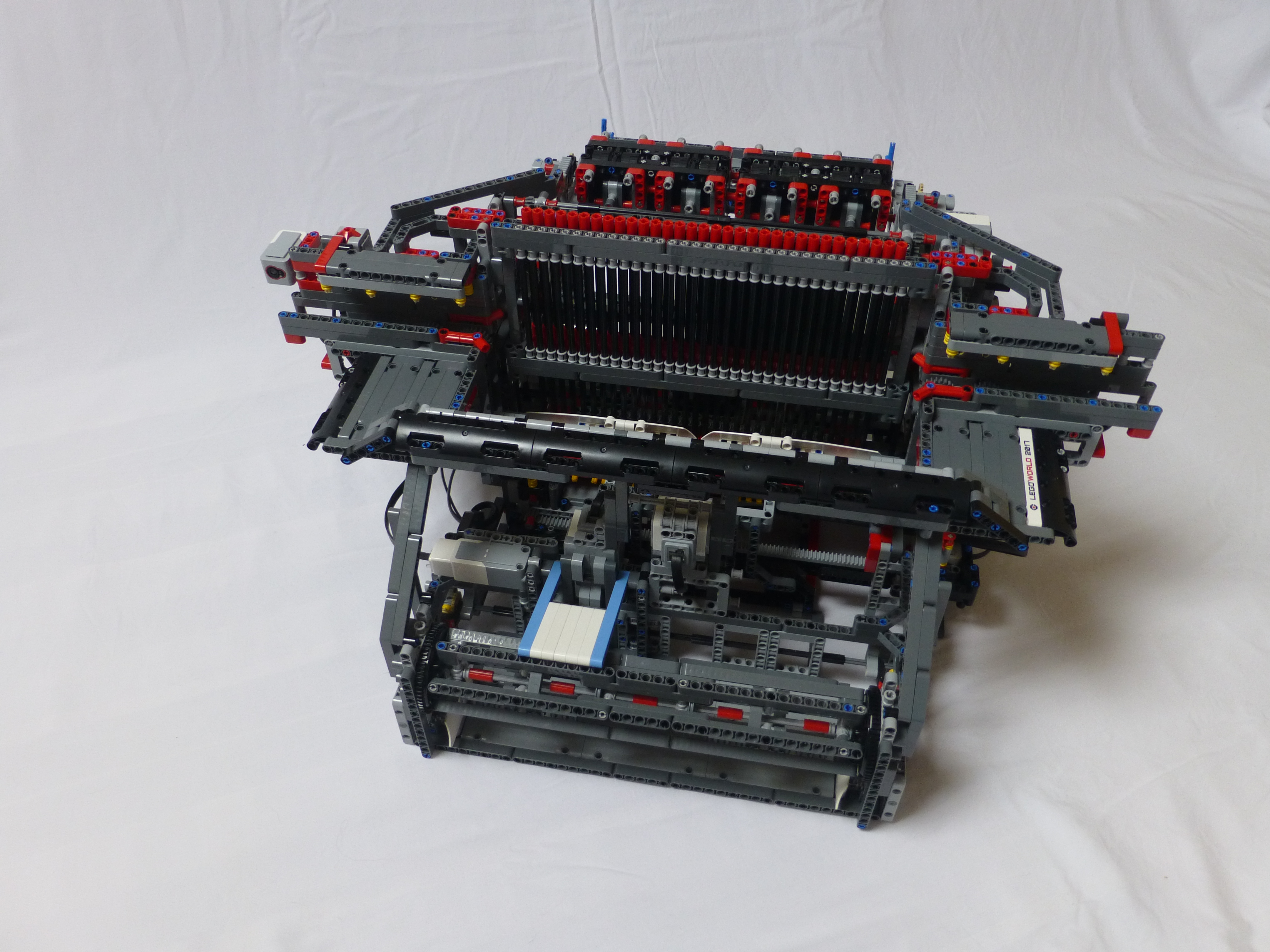
Adding the pinch rollers, bobin frame and support, and bobbin winder all together, the over-all model now looks like:

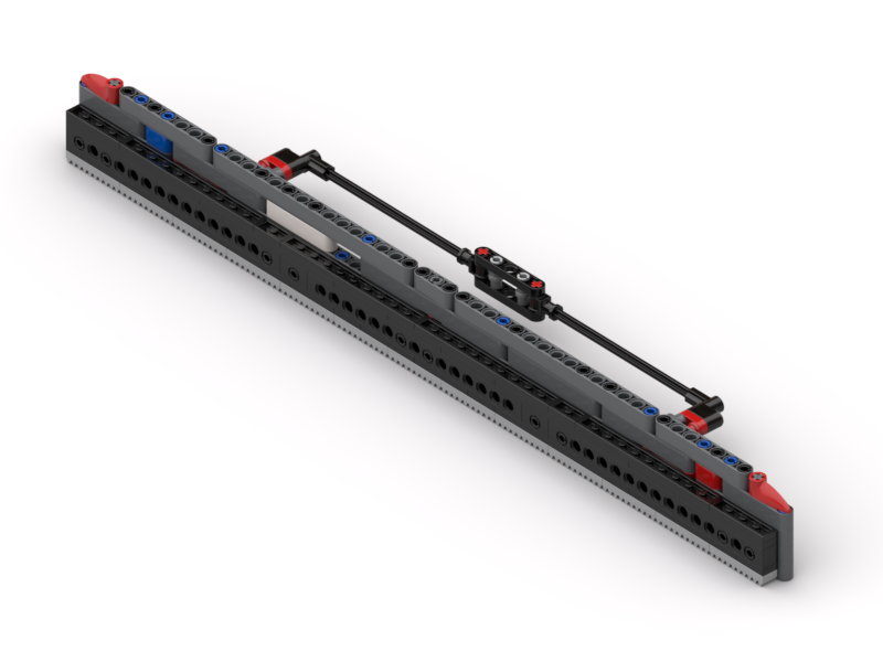
Lifter Bar
Whilst the back of the loom was off – I had to remove the pinch rollers to work out how I’d built them originally – I decided I’d model one of the most important parts of the loom, since it was visible. This is the lifter bar. It is one half of the mechanism that provides the Jacquard ability. It has 32 pins in it, that when one is engaged into the bottom eyelet of a heddle allows that one to be lifted up. There is an equivalent static bar at the front which holds the heddles down if needed.

This mechanism slides up and down along some long axles. These pass through the holes in the ends of the bars, and through some of the holes in the frames. There are gear racks at the back and sides which provide the lifting force. The lifting mechanism has to be offset away from the pins as the pin setting mechanism rides along underneath the whole Jacquard structure.
The LDraw model for this can be found at: http://jander.me.uk/LEGO/loom-parts/Lifter%20Bar.ldr
What Next?
Well, I’m going to put the loom back together, and check that all my new parts actually do what I wanted them to. It’s still loaded with wool from the Mytholmroyd show at the end of January, so I’m going to run that through and then empty the loom.
I’ve then got a little bit of coding to do, to support the bobbin winder – i.e. change the direction of the motor. There’s no need to use the pinch rollers to wind the warp threads on to a drum anymore, so I can repurpose that function to the winder.
I’ve got some other things I need to focus on, and this 3D modelling is quite intensive, so I’m going to take a break from that, and will look to model some more parts in a few weeks time.
Modelling my Loom
Ever since I started to show my LEGO® loom on this blog, Facebook and YouTube, I’ve had people ask me for build instructions. I’ve always said that I’d make them, and I will stick to that … but it’s a BIG task, and will take a long time.
Recently I’ve been making changes to the loom, so have been removing old parts and making new modules to replace them. What I decided to do as I went along was to actually model the parts I was removing, and to model the new parts as I went. This way I have the old parts for reference should I ever want to look back on them in the future, and the new parts have been modelled from the start. As time goes by I intend modelling the separate “modules” of the loom, and then build up a body of work of all the sections. I’ll still need to model the main framework of it, but that will come in time.
So, without further ado, here are the parts I’ve done so far.
Warp Thread Drum
This is the original warp thread winding drum. This was used at the back of the loom and stored the warp threads for feeding in to the loom. In my original build I used to have to wind the warp threads on, en masse, by hand. This suffered from a) being tedious, and b) the threads would wind on at different rates. Since the threads didn’t lie completely flat on top of each other, the drum would end up with different “thicknesses” of threads, resulting in some threads winding on faster than others – since C = 2πr. When the loom was running it’d pull all the threads through at the same rate. Due to the different winding thicknesses, this would either result in some threads getting very slack or, more commonly, some threads getting very very tight.
The LDraw model for this can be found at: http://jander.me.uk/LEGO/loom-parts/Warp%20Drum.ldr
Warp Thread Winding Gearbox
My solution to the differential winding of the warp drum, was to build a set of pinch rollers, that the warp threads went though, and a gearbox that drove the drum.
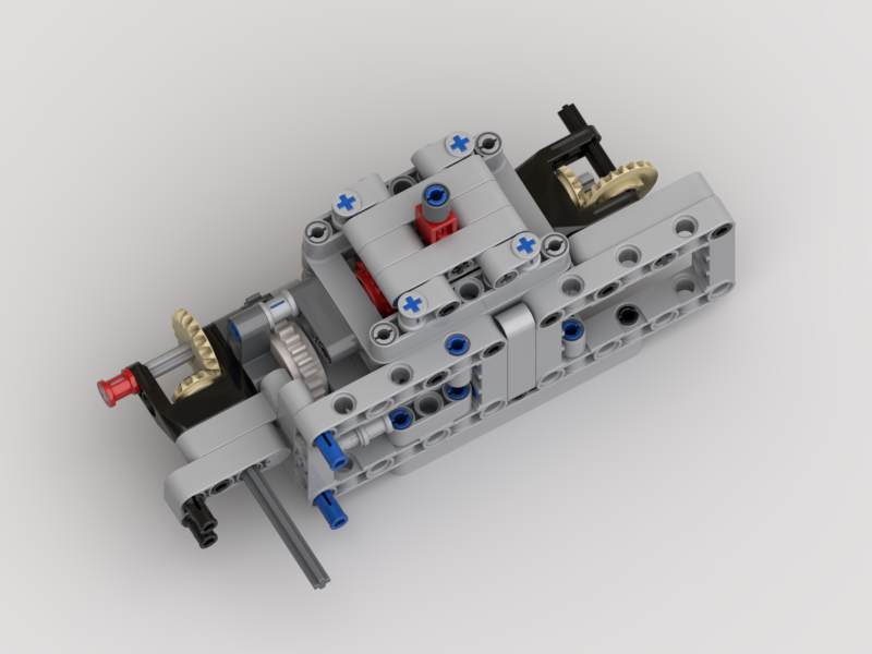
The pinch rollers would be in use during weaving, to provide a tension control between the back of the loom and the cloth take-up drum at the front. They would ensure that all the threads passed through the loom at the same speed.
The gearbox would be engaged when loading the warp drum. When engaged, the warp thread drum would rotate at a “surface speed” ever so slightly faster than the feed rate of the pinch rollers – the white clutch gear would deal with any mismatch in speeds. When weaving the gearbox would be flipped over to a gear with a friction pin, just to stop the warp drum free-spinning.
This appeared to work well, until the last time I loaded the loom. I was struggling with the threads getting caught up in the pinch rollers as they wound on. After watching it load, and thinking on it, it was the same differential speed problem as in the original loom, but in reverse. Now, as the threads wound on, they were winding on at different speeds due to not winding on flat. This was exacerbated by the use of the clutch gear. This meant that the warp drum rotated at the slowest speed, i.e. that of the thickest wound thread. The threads winding on to the thinner areas therefore became slacker, and would get caught on the pinch rollers, ultimately winding back inside them.
The LDraw model for the gearbox can be found at: http://jander.me.uk/LEGO/loom-parts/Warp%20Gearbox.ldr
Bobbin Frame
My answer to the warp threads running at different speeds has been to make a frame that has 32 individual bobbins; one for each thread. I’ve yet to test that it actually works, but will do in the next few days. Now each thread can unwind at its own speed, and not be affected by its neighbour.
I’ve designed a frame that can hold them all, in the manner of a cartridge. This way it can be loaded up away from the loom if desired, and then clipped in to place.
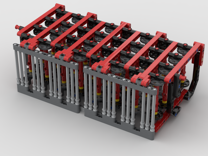
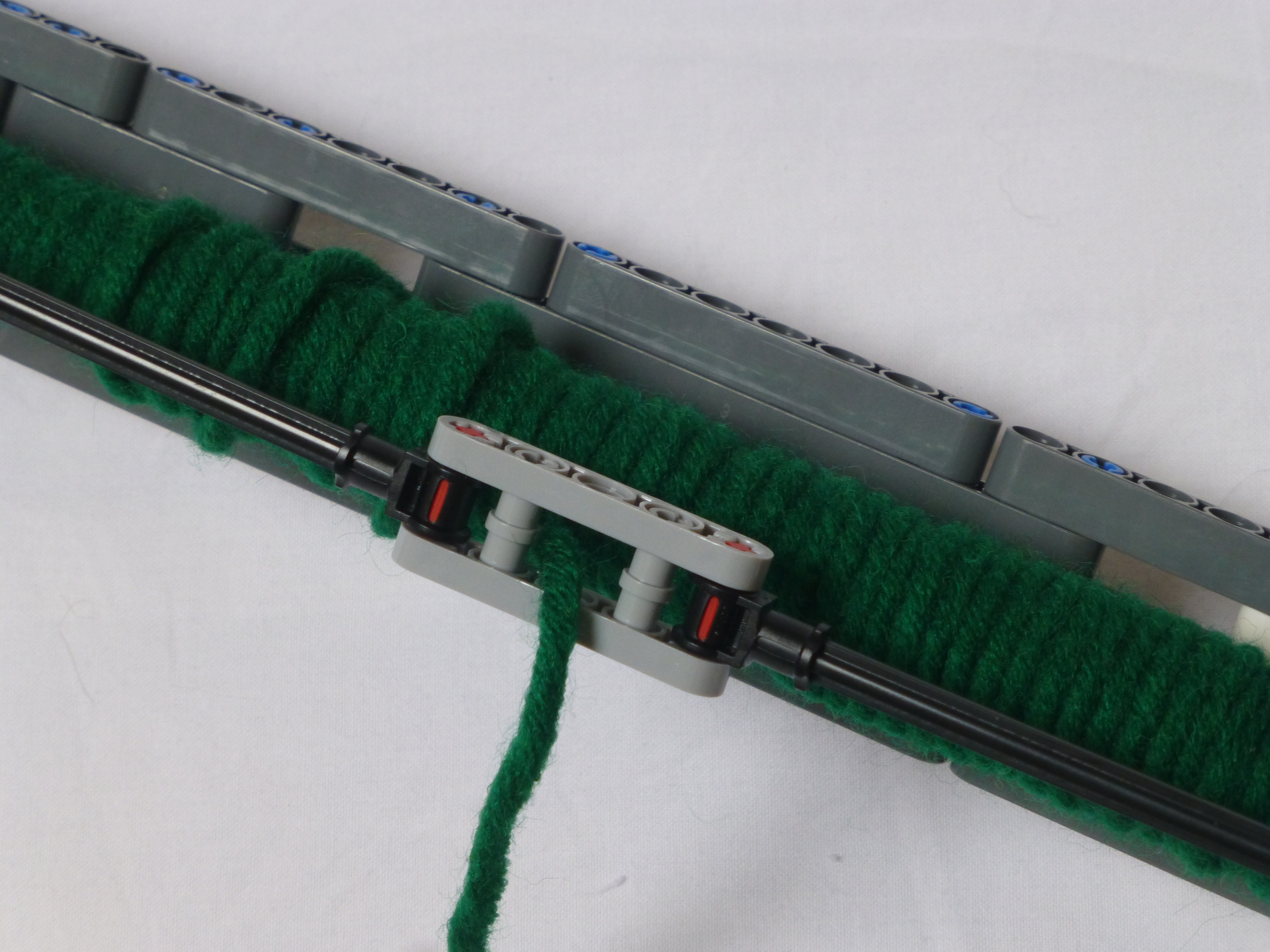
Each bobbin has a black and dark grey disc, and a friction pin on one end and an axle on the other. Half of them have the friction pin on the black side, and the other half on the grey side. The friction pin is simply to stop the bobbin from free-spinning. All the bobbins will be wound in the same orientation with respect to the black/grey discs. This means that when they are all installed half will unwind clockwise, and the other half anti-clockwise. This is so that the threads don’t rub against each other (too much). The frame also has a set of long axles to act as thread separators. This is so that the threads don’t get twisted together, thus preventing them unwinding properly.
The LDraw model for the bobbin frame can be found at: http://jander.me.uk/LEGO/loom-parts/Bobbin%20Frame.ldr
Bobbin Frame Support
To support the bobbin frame and to allow it to be easily removed and installed, a simple support structure was needed.
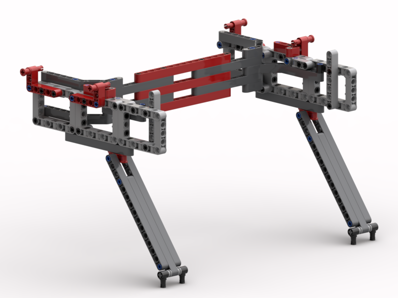
The red pin bushes at the top are used to lock the bobbin frame down on to the support. The bobbin frame itself has axle pins underneath that locate into the angled beams on top at the back. The whole thing is supported on the long angled arms, set at a 3:4:5 Pythagorean angle.
The LDraw model for the support can be found at: http://jander.me.uk/LEGO/loom-parts/Bobbin%20Frame%20Support.ldr
Bobbin Winder
Although I expect to wind the bobbins using my main winder, used for the weft threads, I wanted a winder mounted on the loom itself.
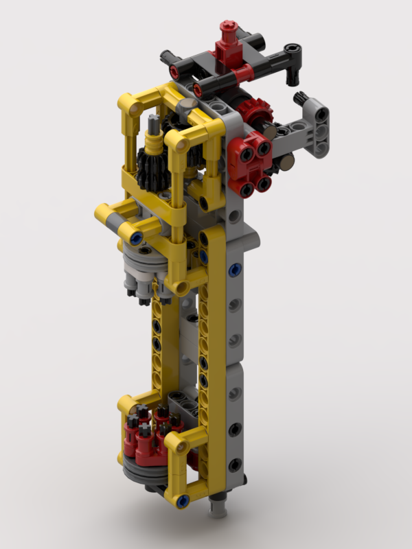
To achieve this a small winder has been made where there are two devices, dog teeth, that engage with the six holes on “wedge wheel” discs on the bobbins. The bottom one hinges out, and the top one slides up and is driven by the same motor that powers the pinch rollers. A single speed gearbox is used to engage/disengage the motor. This allows for it to be used when the loom is empty, and not powered when the loom is in operation.
The plan is to always wind bobbins with the black disc on the bottom, held by the red dog teeth. This will ensure that all the bobbins are wound in the same orientation.
The LDraw model for the support can be found at: http://jander.me.uk/LEGO/loom-parts/Bobbin%20Winder.ldr
Weft Shuttle
Whilst I’ve been working on some of the issues, I thought I’d tackle the shuttle.
This has generally worked well, but now and again has got caught up on the threads as it’s passed through. This has been down the the “shed” (the hole inside the top and bottom warp threads being a little bit too small, and snagging the horizontal bar at the front. This bar is used to ensure that the weft comes out from the middle of the shuttle.
In my original design this bar sat 6L away from the shuttle. The supports that hold that bar in place, and the long bobbin between them, are now 5L and the bobbin sits at 2½L away. It may not make much difference; I have yet to test. If 5L is too short it is easy to modify it back to 6L.
The LDraw model for the shuttle can be found at: http://jander.me.uk/LEGO/loom-parts/Shuttle.ldr
Rendering
I build all my models in Bricksmith. I’ve used it for years, and know how to drive it. I’ve had a play with Stud.io recently, and still don’t (yet) get on with it. However, I really like the renderer that comes with it. So, I’ve been building my models in Bricksmith and using Eyesight, from Stud.io, to make the pictures seen in this article.
What’s Next?
Well, I still need to test that this all works. That’s something for this week, but I think Captain Marvel comes first 🙂
New Weav3r Video
I tried to take some video of the Weav3r loom in operation today – with it empty of threads so that the workings of it could be seen. It hasn’t come out quite how I wanted, but it does show most of what I wanted. I did have a little bit of fun with speeding up parts of it. It sounds quite funny 🙂
Weav3r Loom Update / Photoshoot
I’ve been working on the loom for some time now, trying to iron out some of the issues with it. The main issues were down to the pattern setter, the ‘Jacquard’, getting jammed. This was mainly down to two problems: 1) uncontrolled tension in the warp threads, and 2) vibrations during weaving causing the floating pins to move out of place. To explain these issues, I built a demonstration model.
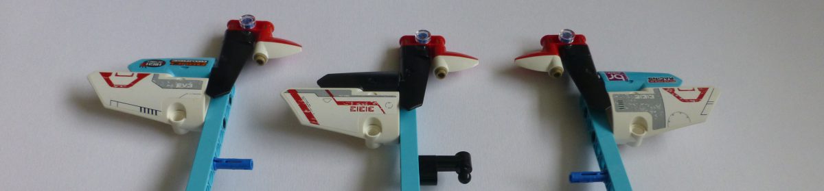
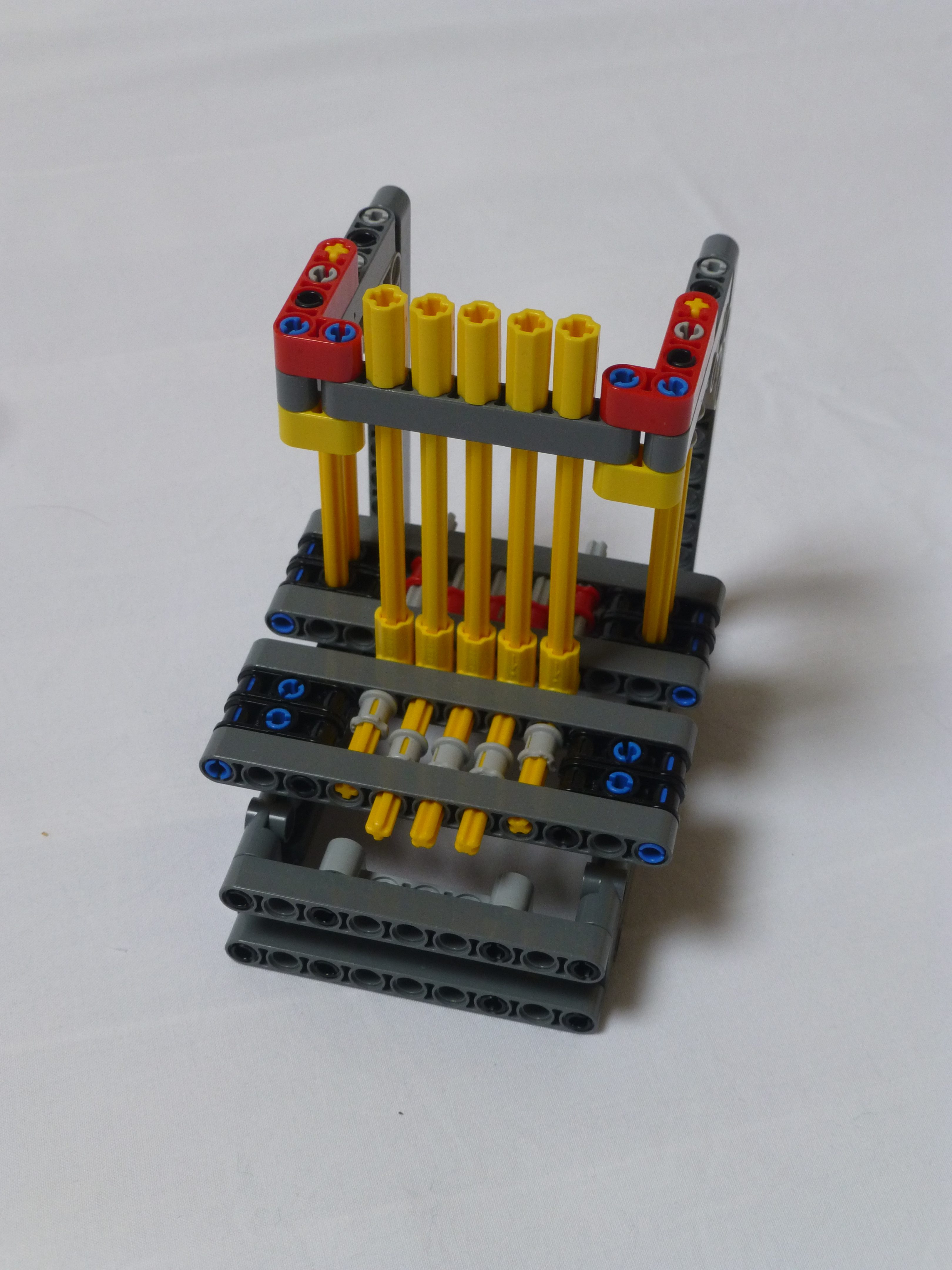
Demonstration
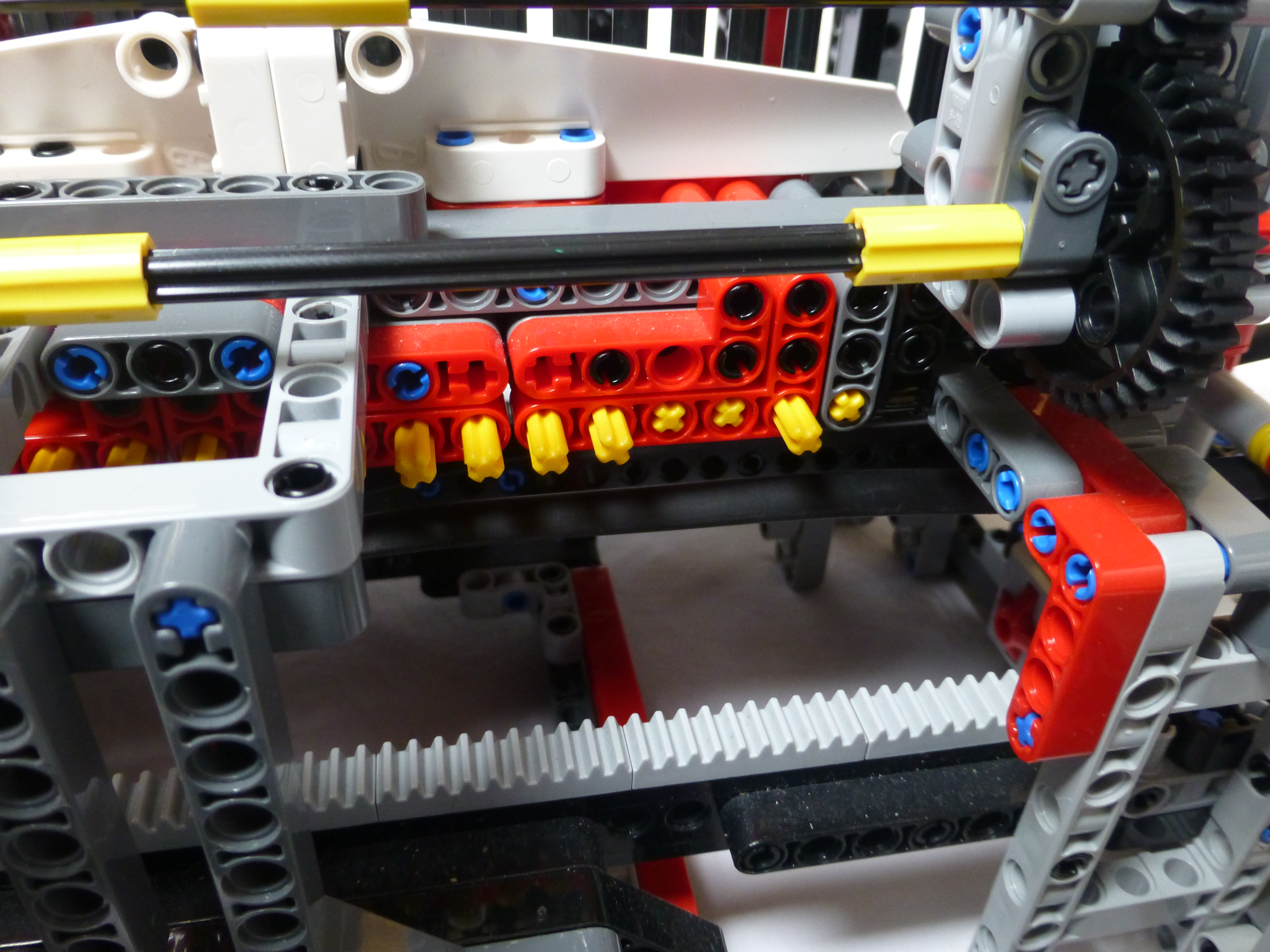
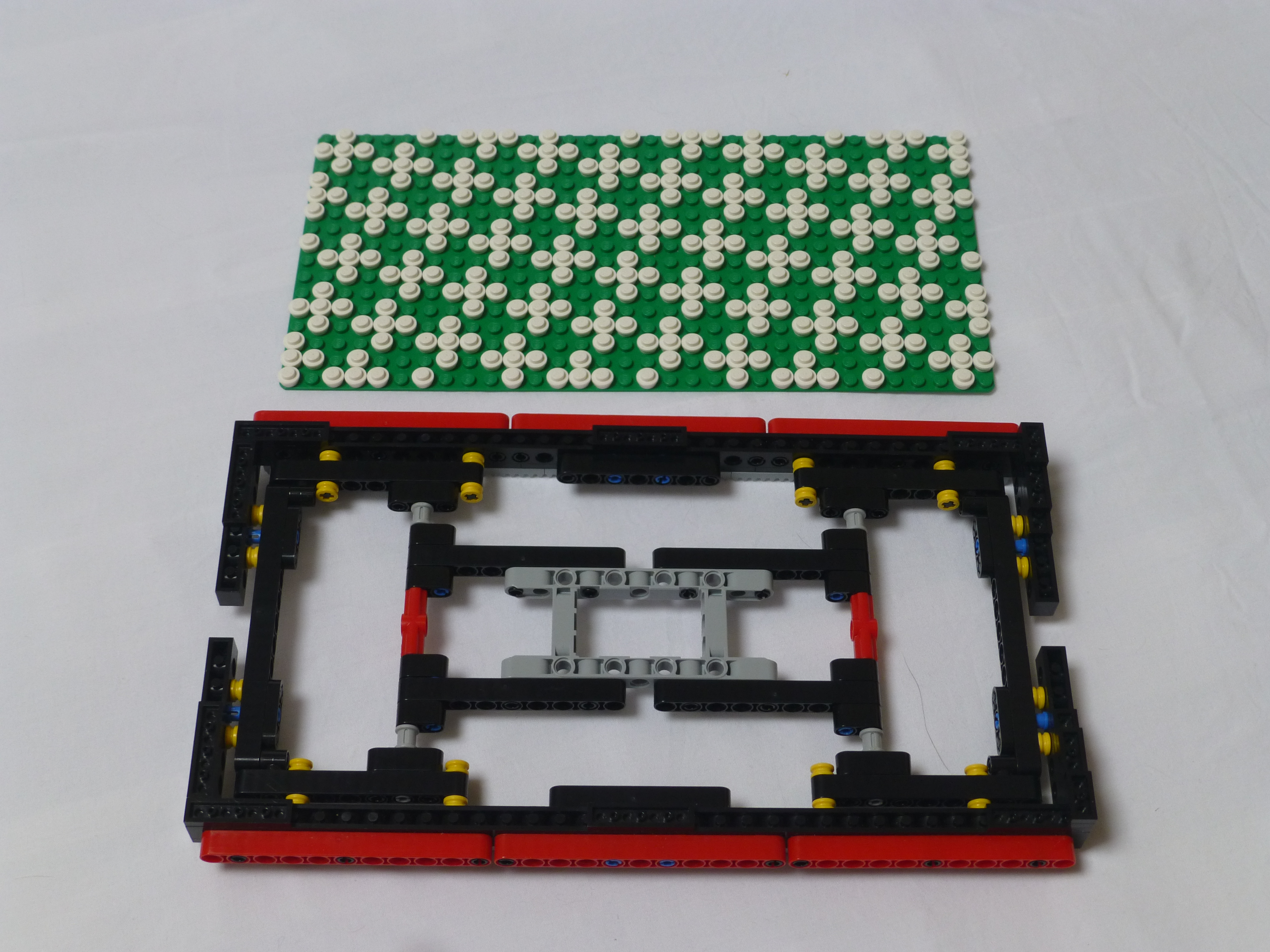
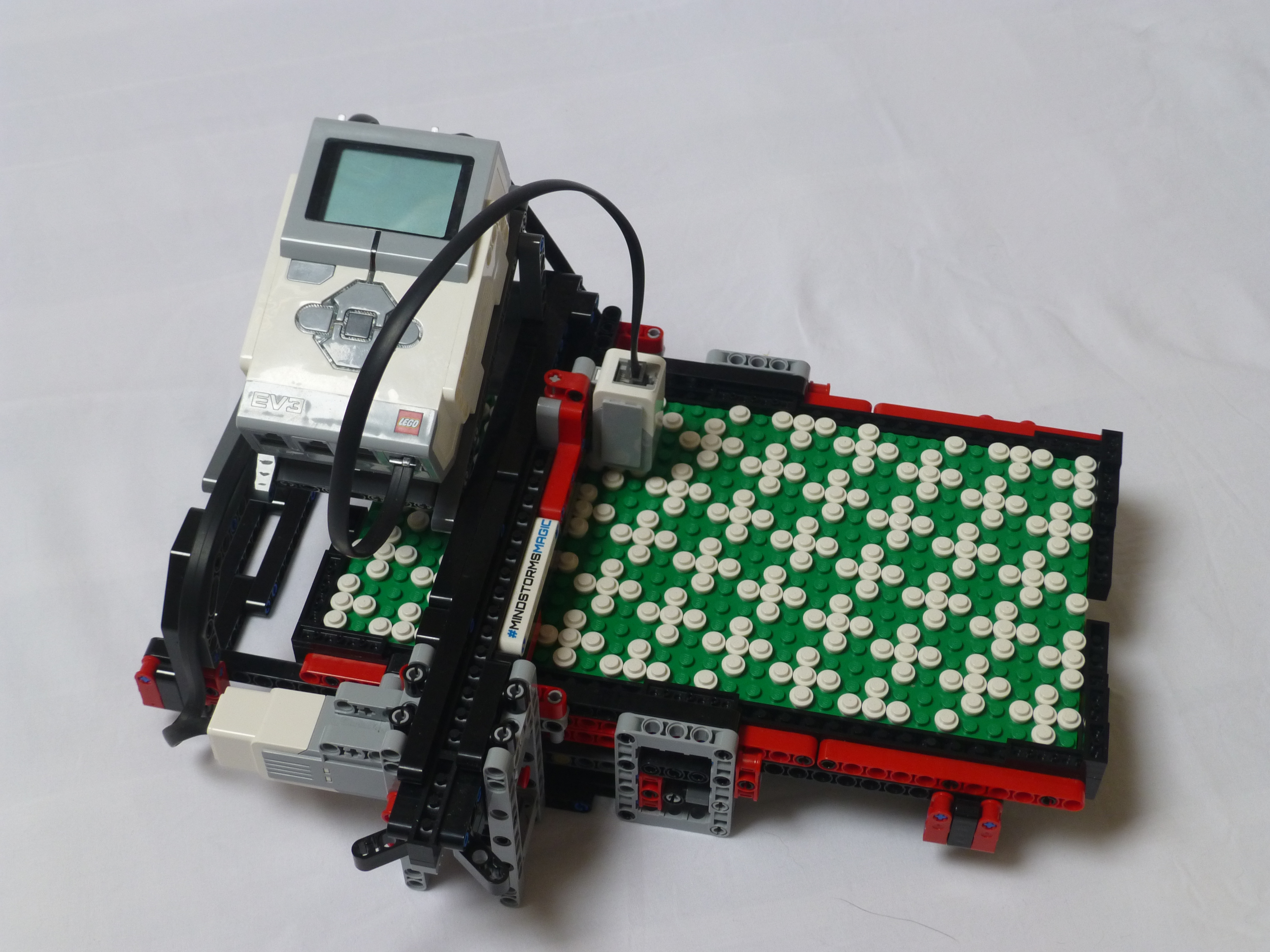
When I’ve shown the loom off at exhibitions, I’ve struggled to explain, easily, how the pattern setting mechanism works. So, to make it simpler I built a little model of the mechanism, as shown in the picture below. There are two beams with floating pins inside. The picture below shows the front beam with 3/5 of the pins set forward. The beam behind the vertical yellow axles, the “heddles”, can lift upward.
The picture below shows the lifting beam in the upmost location, thus showing how the patterns are set on the heddles.
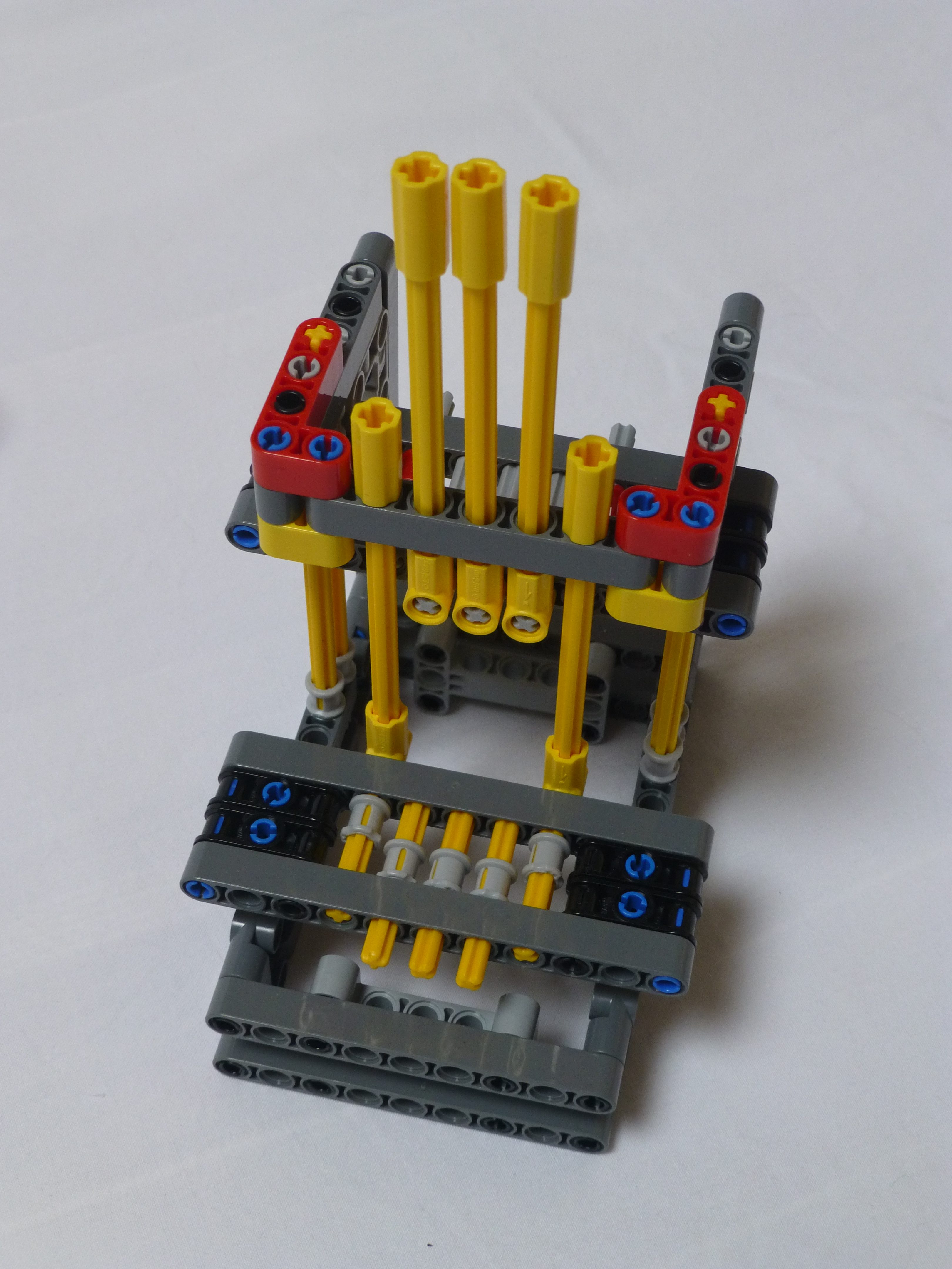
Both of the pictures above also show where the problems with the loom occur.
Problem #1
The first problem is when setting the pattern. The loom needs the heddles to be in their lowest position for the pins to move back and forth. In the original build of the loom, there was only one way of maintaining tension in the warp threads which was by applying friction to the warp thread supply drum. Due to how the loom was loaded with threads, and this drum wound, it was probable that the tensions would be mismatched across the threads. As the loom worked though row by row, some threads could end up much higher tension than the others. This would cause issues when the setter beam needed to drop as it couldn’t pull down against that tension, resulting in the setter beam being slightly crooked. When the pin setter tried to move the pins, they would not line up with the rear bar’s holes resulting in the entire mechanism jamming up.
Problem #2
The second picture shows how the vibrations could be a problem. As the shuttle would pass from side to side there would be a small amount of vibration, or buzz, from the motors. This would cause the unsecured pins on the front beam to precess backwards, under the heddles that had been lifted. Again, when the bar was lowered it would not be able to move to its lowest position due to these precessed pins blocking its path.
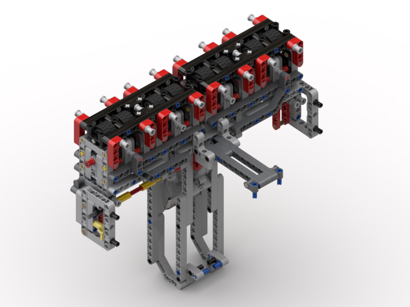
Solution #1
The solution to problem #1 was to build a complete replacement to the original thread tensioner. This time a set of 8 driven pinch rollers was implemented, along with a gearbox to control the warp thread supply drum.
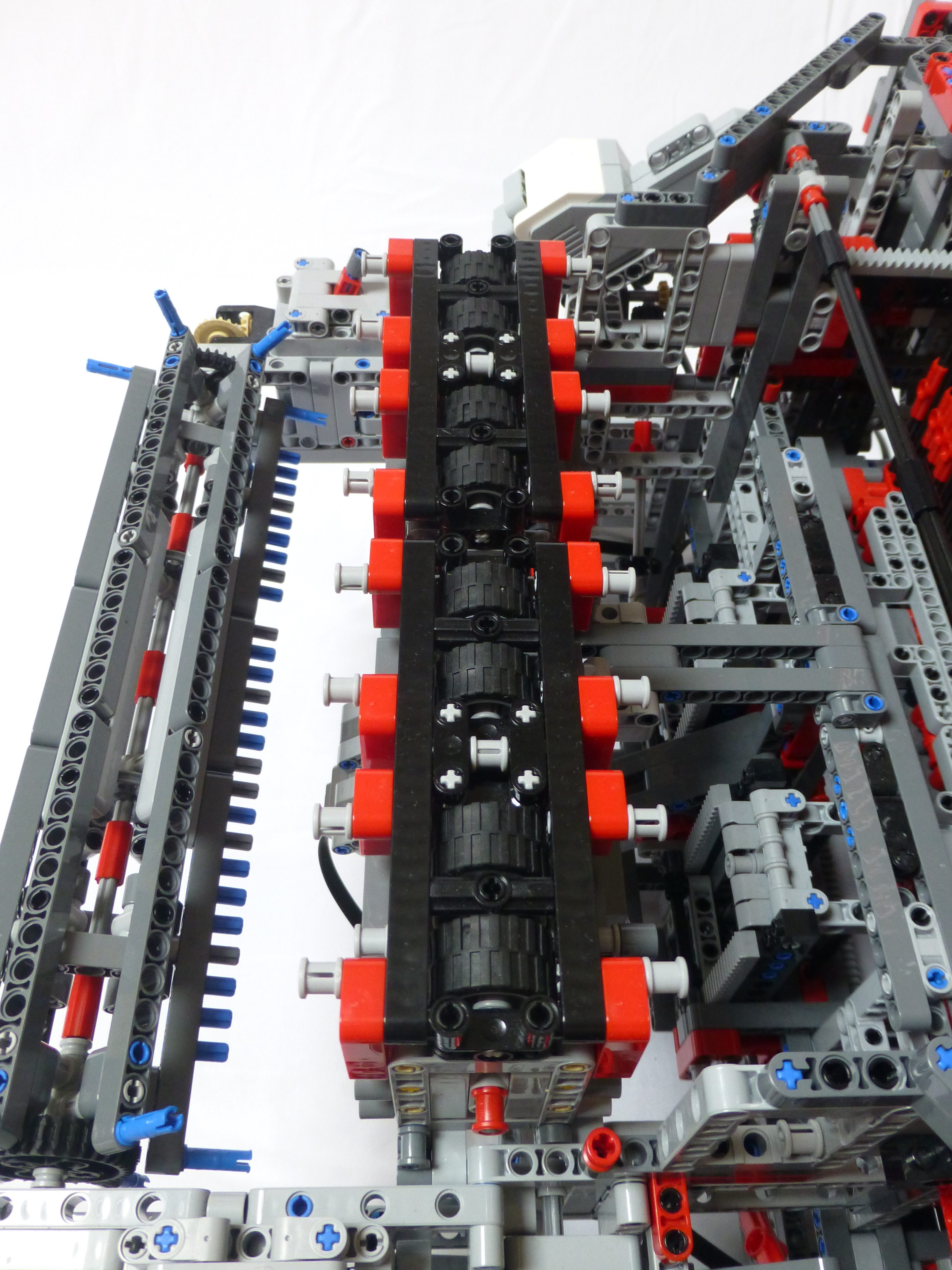
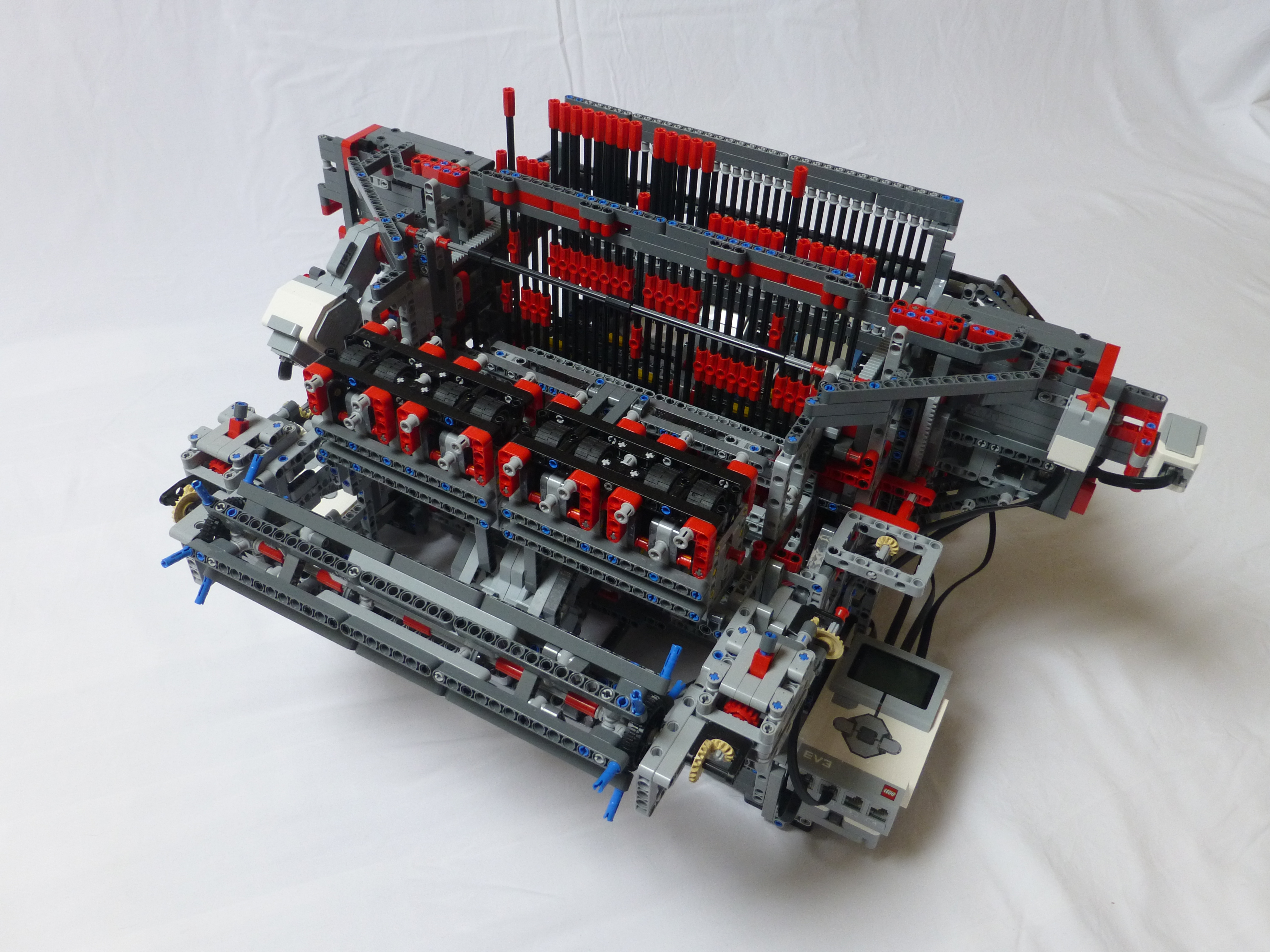
The picture above shows the new pinch rollers and the warp supply drum. There is a gearbox, shown in the picture below, that connects the drive of the pinch rollers to the warp supply drum.
When the gearbox is selected in one direction the supply drum rotates very slightly faster than the pinch rollers, with a white clutch gear for protection. This allows for much faster loading of the loom. The threads can be placed in the rollers and clamped down, and then tied to the drum. The loom can then be set to wind the threads up on the drum, with all threads at equal tension. Moving the gear to the other selection connects the drum to a gear on a blue axle pin. This simply applies some friction to prevent the drum from spinning uncontrolled as the loom weaves. Neutral allows for rapid removal of threads when needed.
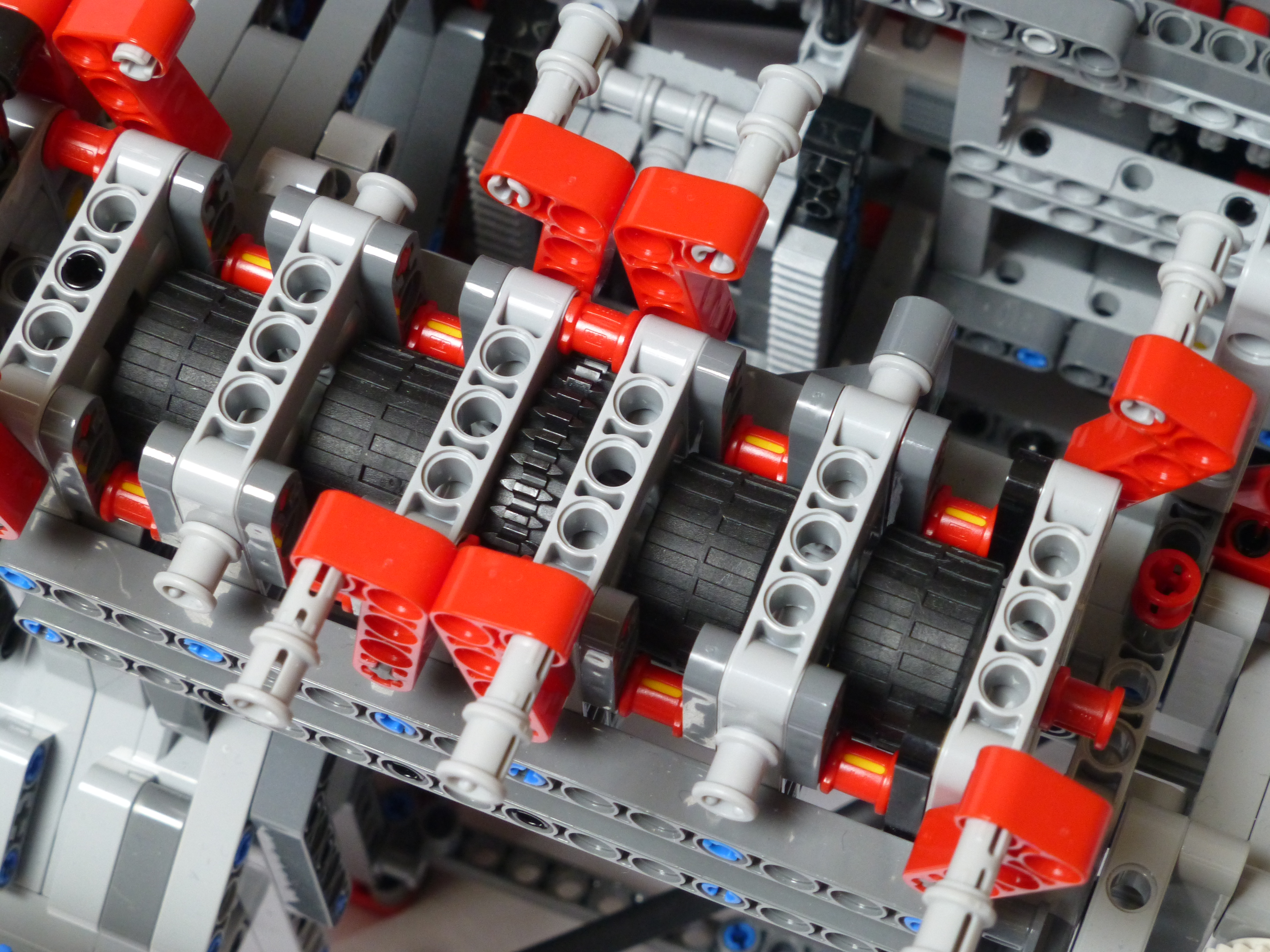
The lower pinch rollers, as shown above, are all driven by a large EV3 motor. When weaving, just before the heddles are lowered, these rollers will move the thread forward by one weft thickness (adjustable during operation), thus lowering the tension in the loom. Tension is restored when the cloth is wound forward on to the take-up drum at the front.
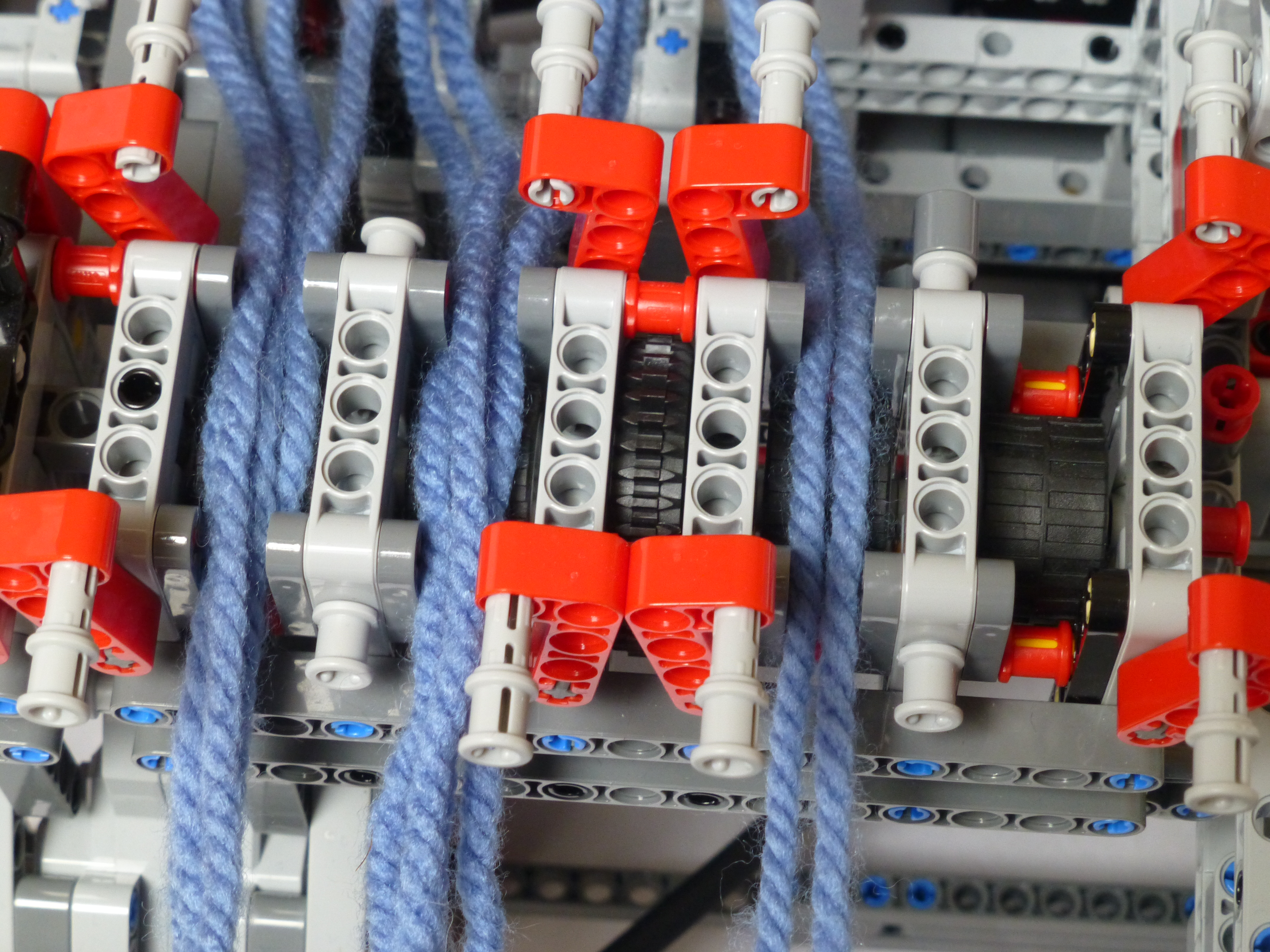
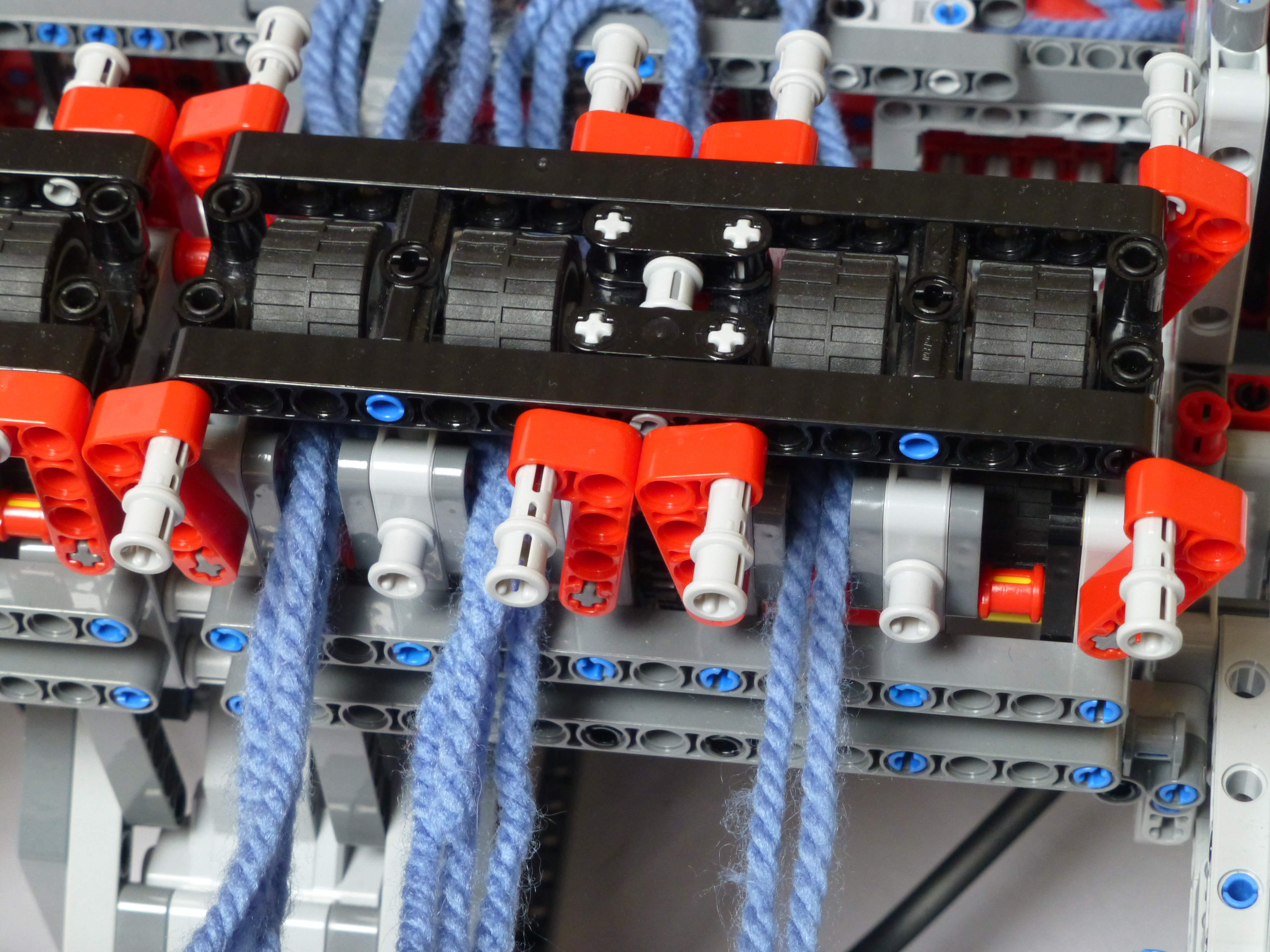
Loading the threads is simple – 4 threads per pinch roller, and then clamped in place with the top rollers as shown below.
Solution #2
Various solutions to the vibration problem were tried, most involving attempts to increase the sliding friction on the pins. None of them worked; no solution to applying just a little friction in a LEGO-only manner could be found. Instead, the simple solution of tilting the loom slightly forward was tried. This would mean that if the pins were to precess, that they would move forward rather than backward due to the slight slope. Raising the back of the loom up by 1.5M over a distance of 48M is just about 2°, so not a massive tilt, but just enough. The beams running under the loom, as shown below, give that tilt.
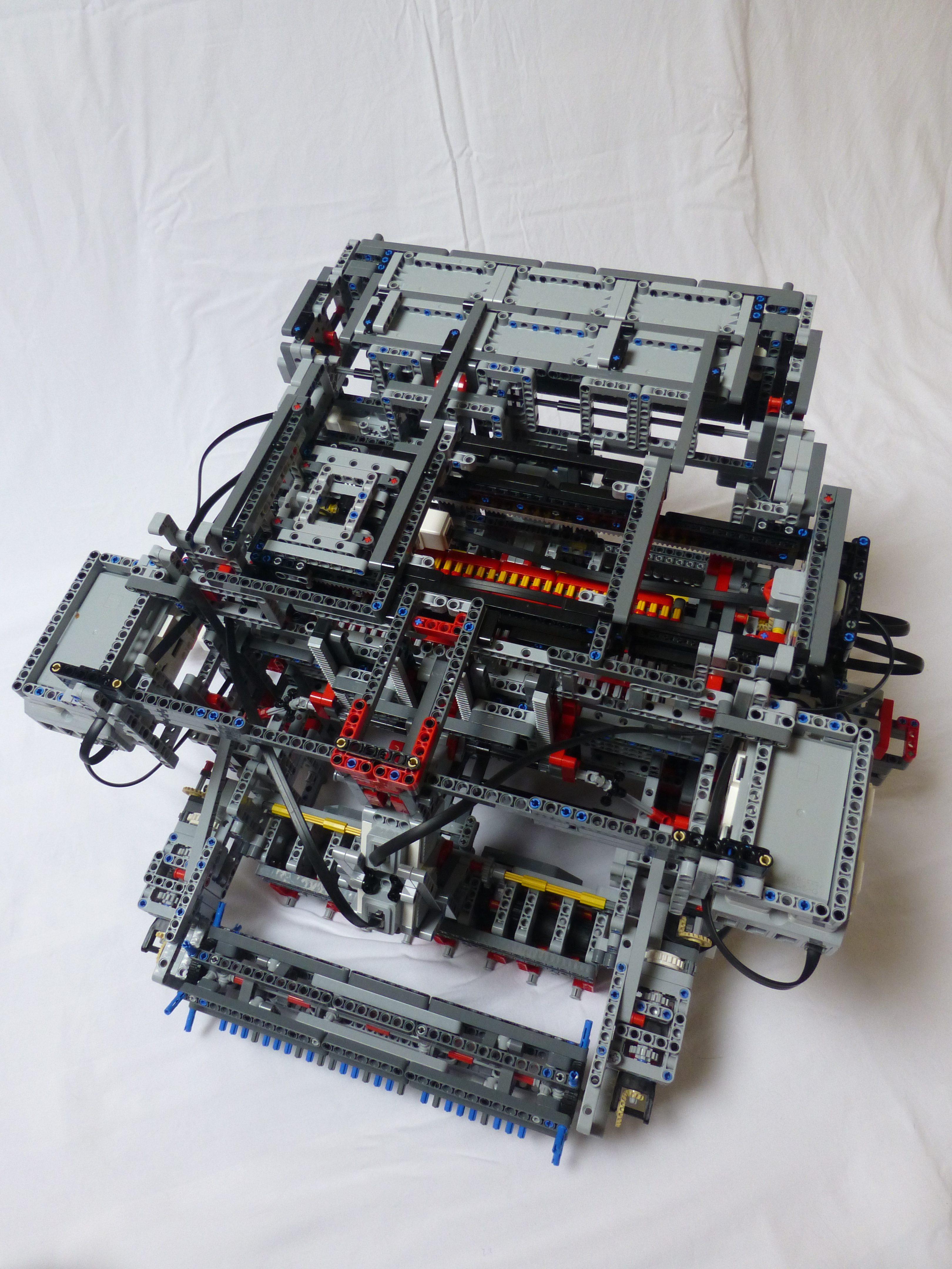
Photoshoot
Whilst I was taking pics of various parts, I decided to take (hopefully) some good pics of the rest of it whilst I was at it. I include those below.
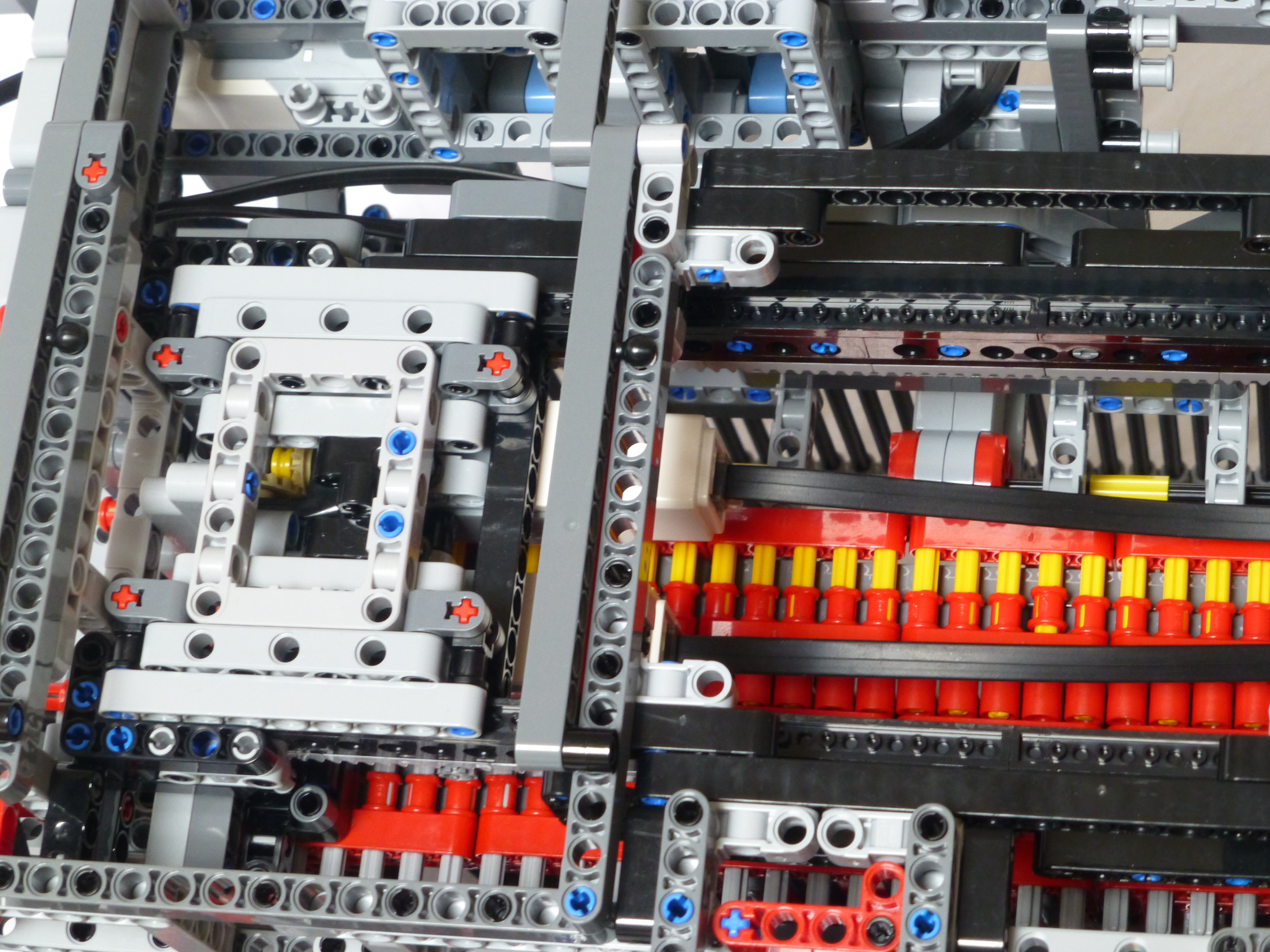
The grey racking at the front of the picture above has a partner rack at the back. This is used by the pattern setter to move left and right.
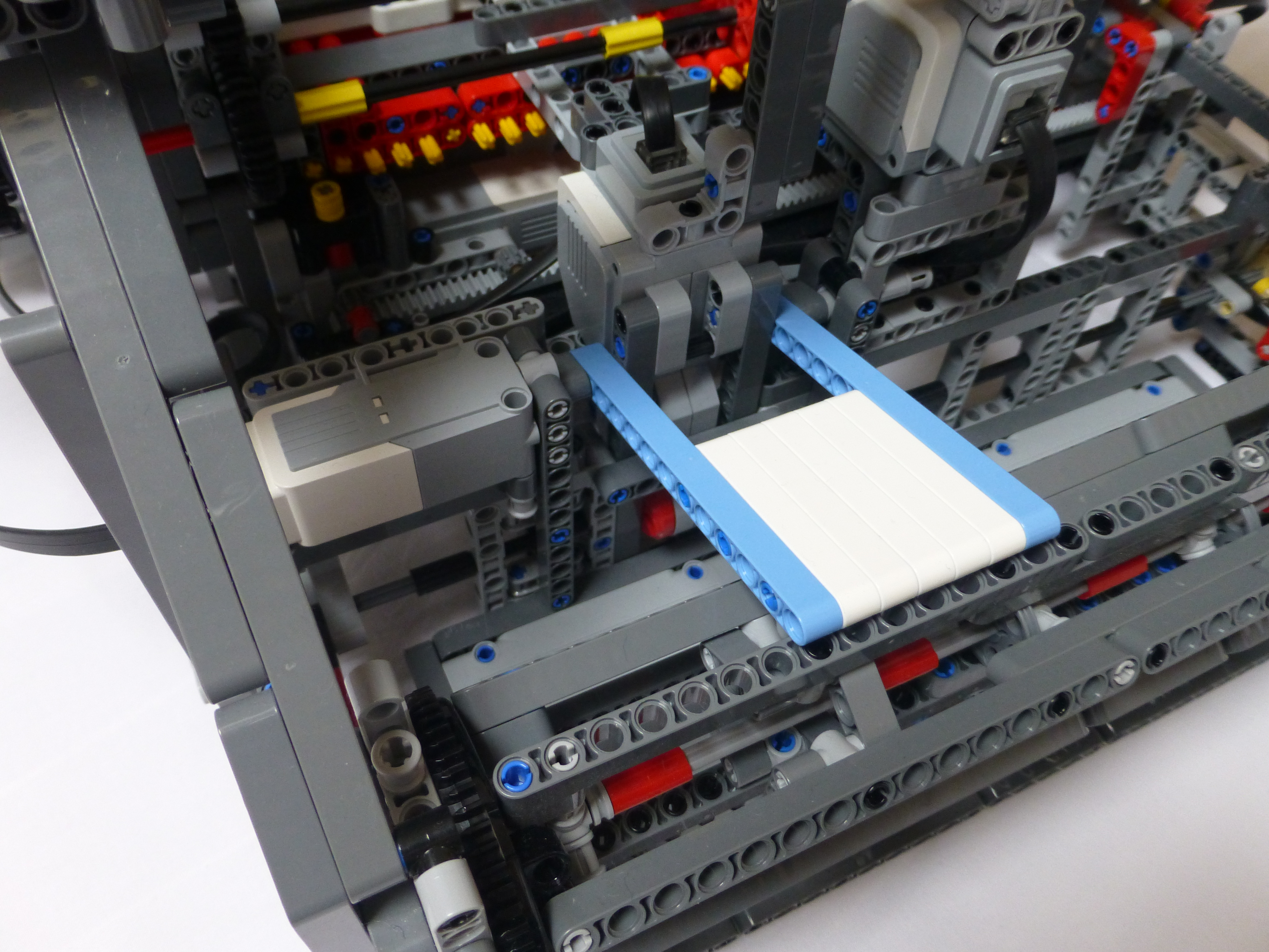
The white and blue flap above is connected to the medium motor. After each pass of the shuttle, the motor lifts the flap, and then lowers it gently until it stalls. The motor angle is then used to compute how wide the cloth take-up drum has become. That in turn is then used to compute the angle of rotation needed to ensure a consistent movement of the cloth, i.e. the width of the weft. This should be the same distance as the pinch rollers will move. The thickness of the weft can be adjusted during operation, along with minor adjustments to the drum and pinch roller positions.

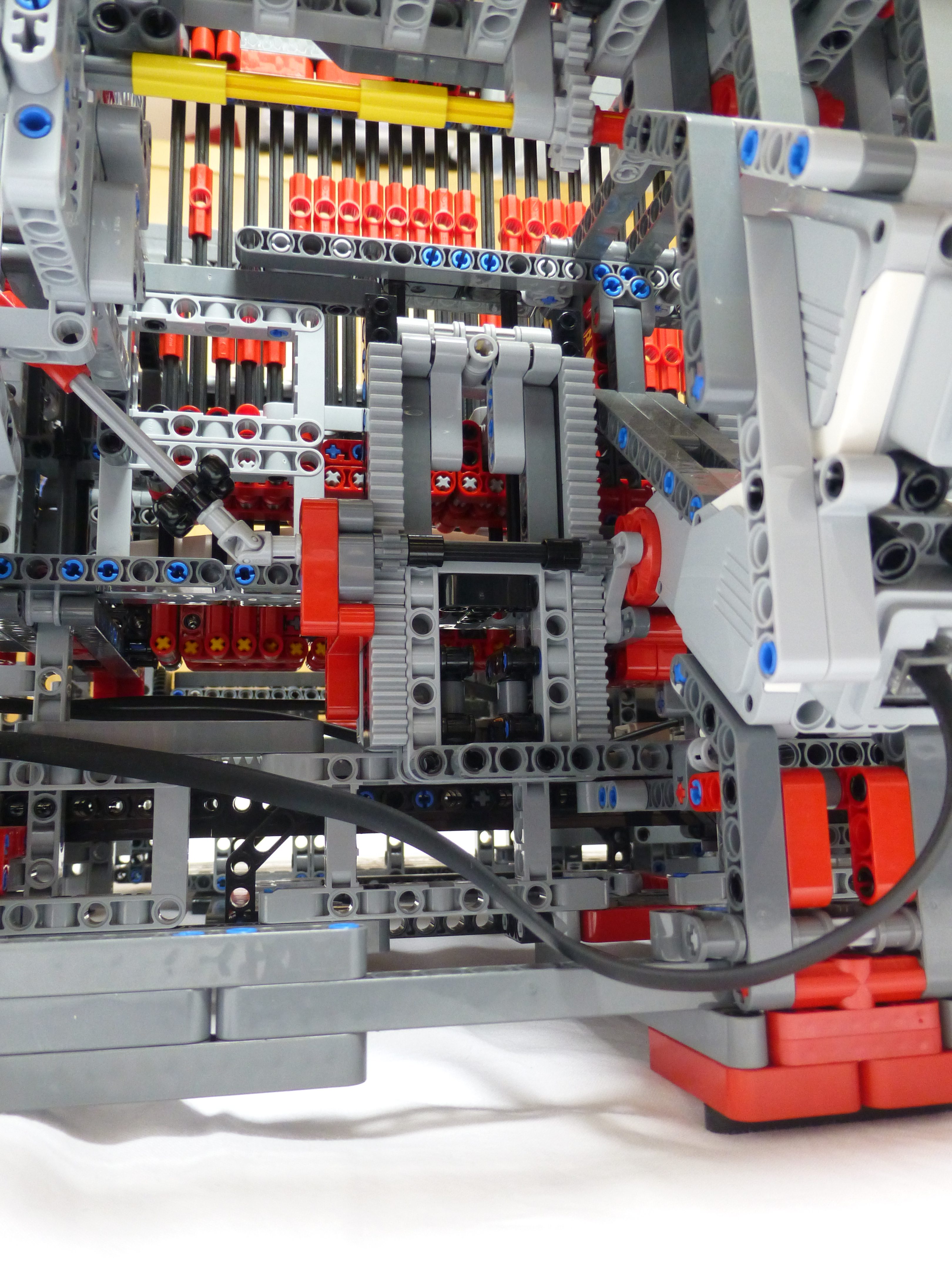
The picture above shows part of the rear beam lift mechanism. There is an identical rack on the righthand side of the loom, along with lifting racks at the ends of the beam.
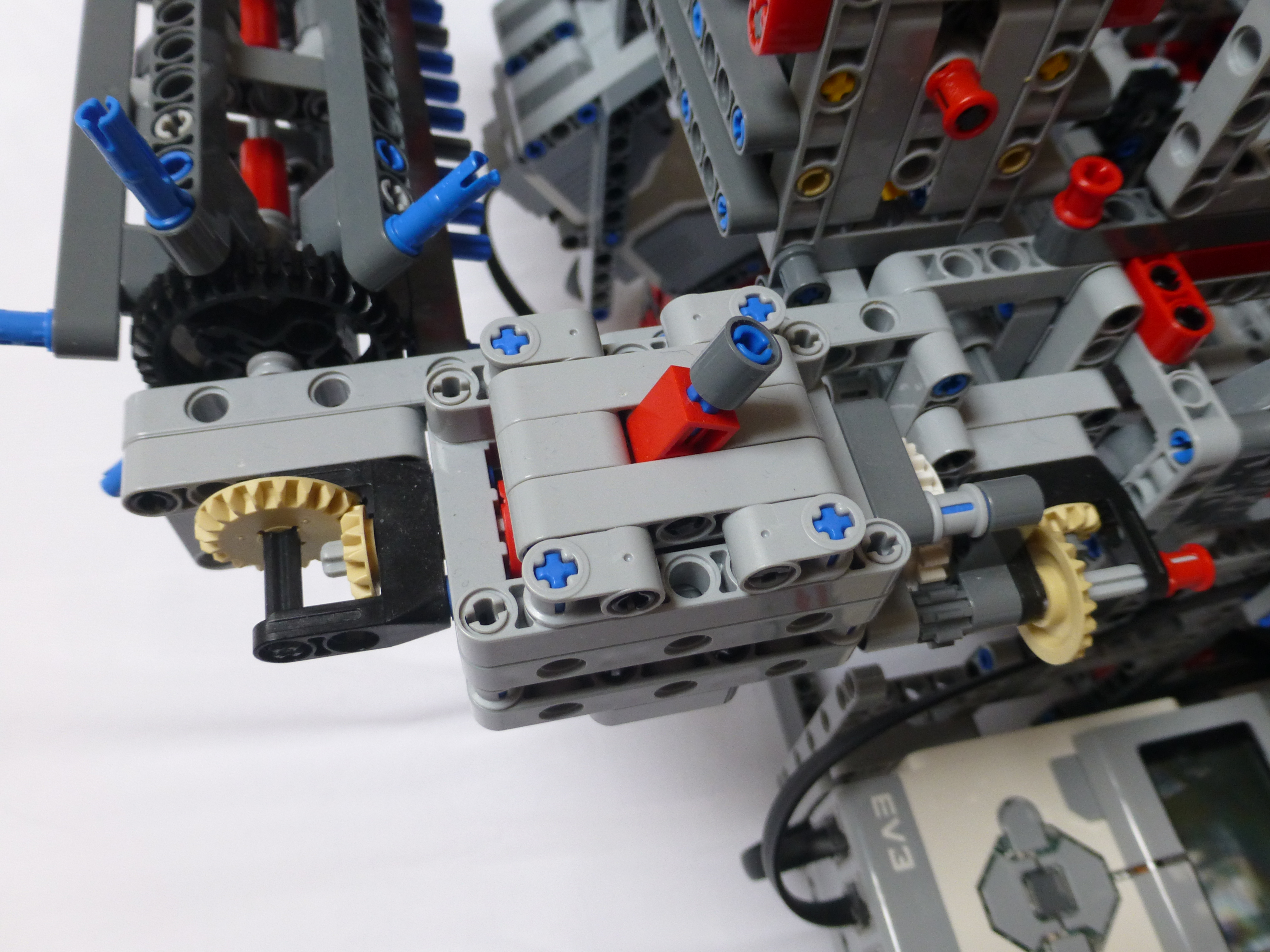
The light grey structure is the bottom of the pin setting mechanism. This moves left and right, under the pins, pushing the pins back and forth. It is programmed to set the pins in both directions, rather than returning to the ‘start’ on each shuttle pass.
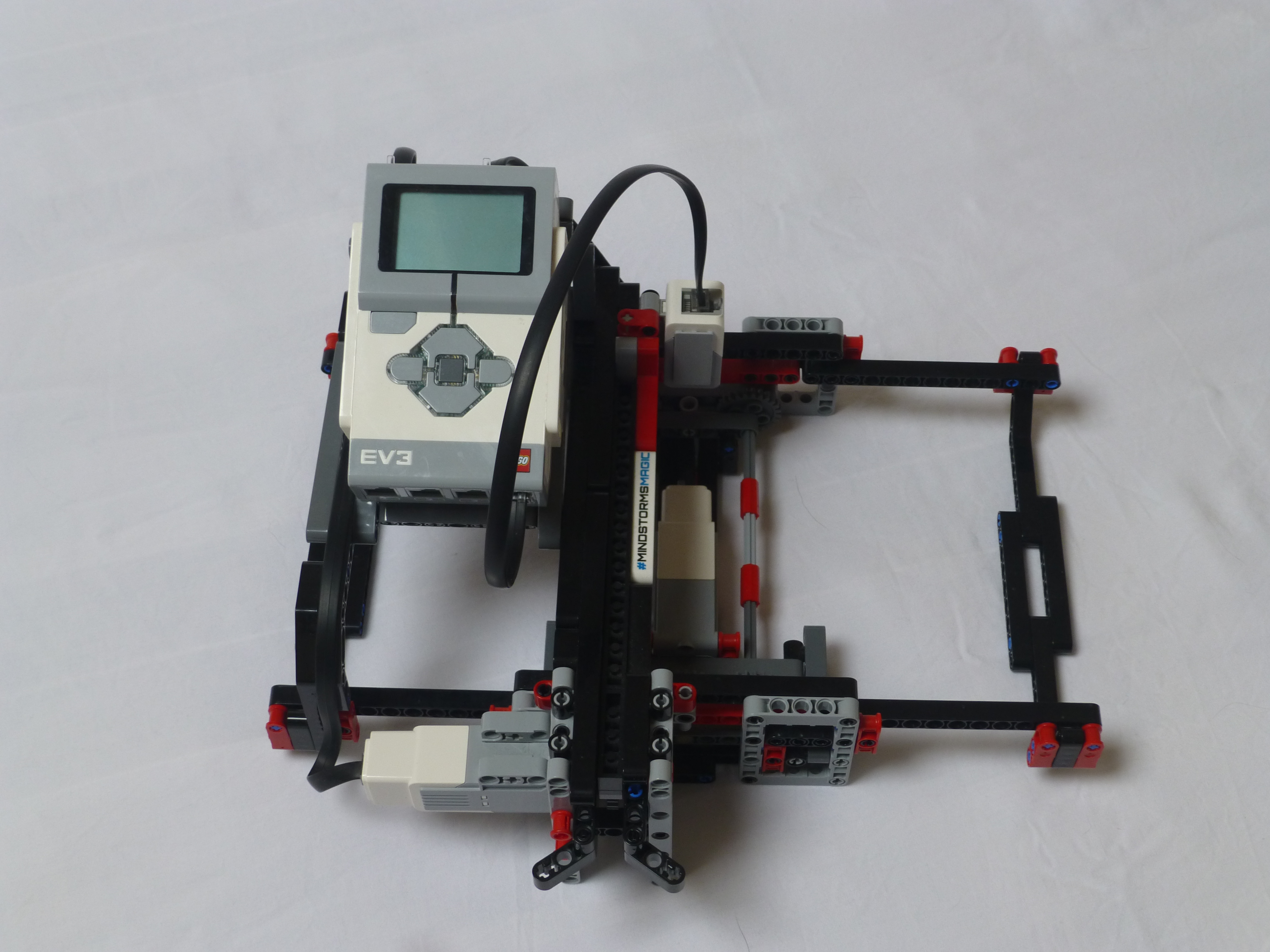
The entire loom is controlled by the EV3 shown above. Bluetooth is used to coordinate the actions of the other two EV3s. One EV3 manages the heddles setter (2 motors), heddle lifter (1 motor) and the reed (1 motor). The other EV3 manages the shuttle (1 motor), pinch rollers (1 motor), cloth wind drum (1 motor) and drum sensor (1 motor).
The pattern boards can be used to set up what to weave. They are 16×32 boards, with the pattern woven across the middle 16 warp threads, using 32 wefts. A plain “up, down, up, down” pattern will be woven into the 8 threads either side of the board’s pattern to ensure that the cloth remains in shape.
I’m hoping to take some videos of the loom in action next week and will post them to YouTube.
Further AI2/EV3 Bluetooth Coding
As my recent posts, Receiving BT Mailboxes from EV3 by an AI2 App & Updated BT comms between EV3 and AI2, have indicated, I’ve been working on getting AI2 app sending and receiving EV3 Mailbox messages via Bluetooth.
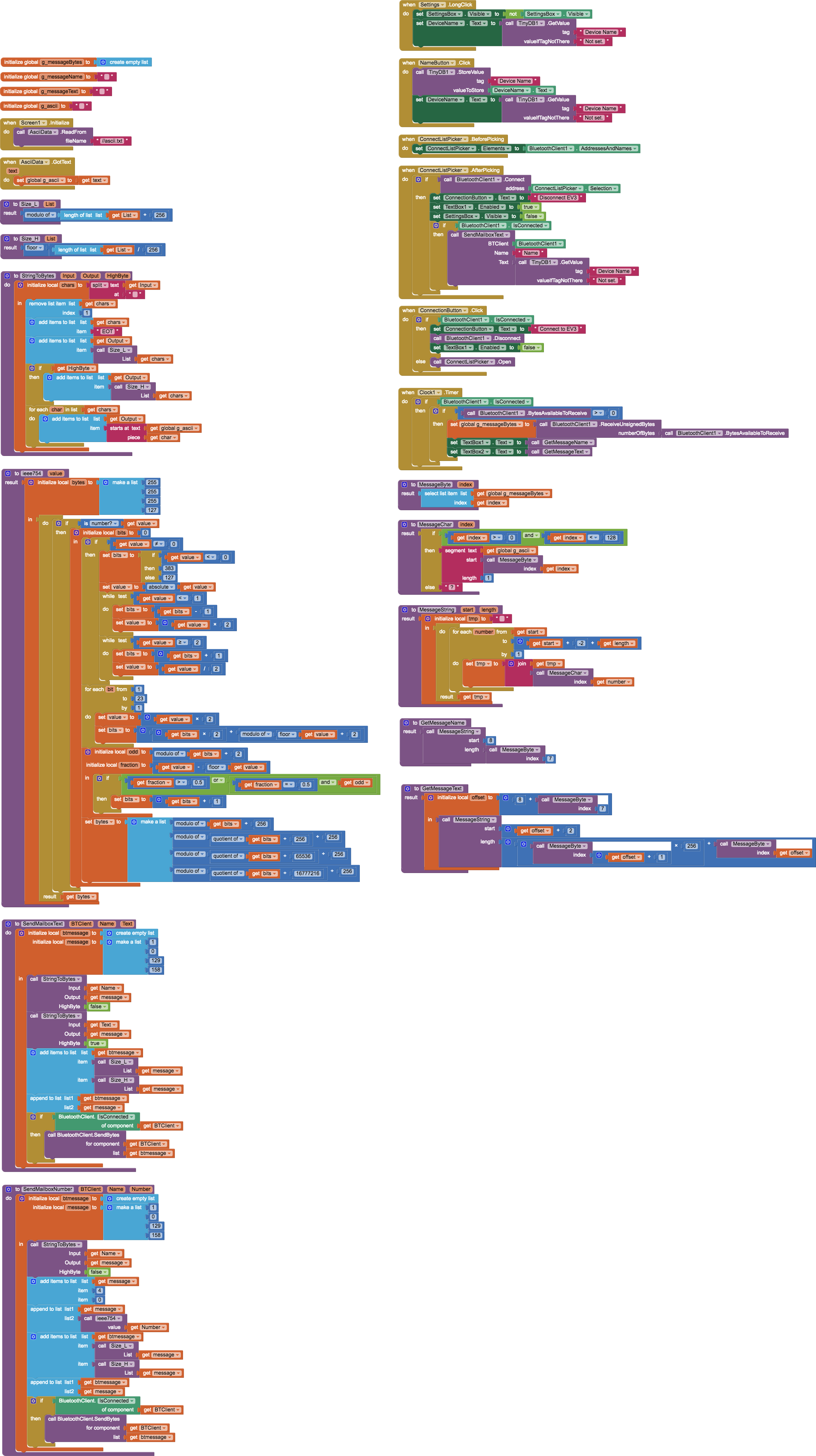
One of the annoyances I’d had is that the EV3 needs to know the name of the AI2 device in order to send messages to it. Up until now that name has had to be entered in to the AI2 app by the user. This of course is prone to error in different ways. There wasn’t a way of getting this information via the available AI2 components. So, I’ve added to my EV3Mailbox extension. It now has a GetDeviceName call which will extract that information to be used however one wishes. In my code I use this name to send a message to the EV3 on connection, for it to use in return messages. Example AI2 code is as below:

Downloads
As usual, I am making my code available for use under the Creative Commons Attribution-ShareAlike 4.0 International License
The sample .aia file should include the extension .aix file, but I am also making that specifically available for use in other people’s projects.
- Run the EV3 code first.
- Start the AI2 app.
- Press “Connect EV3”. This will give the list of BT devices known the the Android device. Choose the correct EV3.
- Once the App is connected to the EV3, the EV3 will say “detected”.
- Pressing the top, middle, or bottom buttons on the EV3 will send a BT message to the App:
- A string for the top button
- A number for the middle button
- A boolean for the bottom button.
- The App will then display the message name and contents in the top two boxes.
- You can send string, number or boolean values back to the EV3 via the relevant boxes and buttons.
Updated BT comms between EV3 and AI2
Recently I posted about sending Bluetooth messages from and EV3 to an AI2 app. I decided at the time not to bother considering handling receiving IEEE754 floats as strings would work. Since then I have been thinking about how cluttered the code was, and that AI2 doesn’t easily support libraries of AI2 code. So, I started investigating writing a simple EV3Mailbox extension for AI2. After a bit of learning Java (I’m a Perl programmer at heart) I now have an extension:
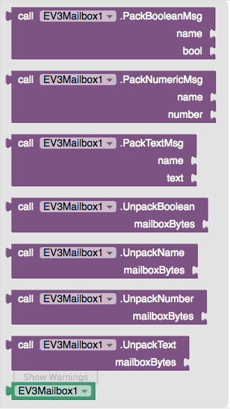
The extension is still quite simple, solely handling the packing and unpacking of the message bytes. The Bluetooth comms part will still need to be performed by AI2 code. An example of using this to send/receive messages is as below:

Downloads
As usual, I am making my code available for use under the Creative Commons Attribution-ShareAlike 4.0 International License
The sample .aia file should include the extension .aix file, but I am also making that specifically available for use in other people’s projects.
- Run the EV3 code first.
- Start the AI2 app.
- Long-press the BT button. This will bring up a settings box.
- Enter the App device’s Bluetooth name in the settings – and press ‘save’. This will be stored, and sent to the EV3. This is so that the EV3 knows where to send its messages to. This must be the same name as shown in the BT connections list on the EV3.
- Press “Connect EV3”. This will give the list of BT devices known the the Android device. Choose the correct EV3.
- Once the App is connected to the EV3, the EV3 will say “detected”.
- Pressing the top, middle, or bottom buttons on the EV3 will send a BT message to the App:
- A string for the top button
- A number for the middle button
- A boolean for the bottom button.
- The App will then display the message name and contents in the top two boxes.
- You can send string, number or boolean values back to the EV3 via the relevant boxes and buttons.
Receiving BT Mailboxes from EV3 by an AI2 App
Recently, on the MINDSTORMS Facebook group, the question was posed about is it possible to receive Bluetooth mailbox messages in an AI2 app from an EV3. This is something I’ve been meaning to do for a while. I’d written AI2 code to send BT messages to an EV3, but hadn’t focused on receiving messages. This was the spur to actually get this code written.
It wasn’t too tricky. Receiving the message was simple, but parsing it was the harder part. The format of a message from the EV3, as covered in my update to BT messaging is:
MLenL, MLenH, 0x01, 0x00, 0x81, 0x9E, NLen, NameBytes, 0x00, TLenL, TLenH, TextBytes, 0x00
This is received as a string of bytes, so has to be parsed as a list. Add in that there doesn’t appear to be a chr(x) type function in AI2 to convert from a number to its equivalent ASCII character, I have to do some array/list lookups. Thankfully I had that code in place for sending to the EV3.
Code
I’ve got the code to a position that it can hopefully be used for other purposes. I’m releasing what I’ve done so far as a baseline for others to work from. To make the code, linked below, work do the following:
- Run the EV3 code first.
- Start the AI2 app.
- Long-press the BT button. This will bring up a settings box.
- Enter the App device’s Bluetooth name in the settings. This will be stored, and sent to the EV3. This is so that the EV3 knows where to send its messages to. This must be the same name as shown in the BT connections list on the EV3.
- Press “Connect EV3”. This will give the list of BT devices known the the Android device. Choose the correct EV3.
- Once the App is connected to the EV3, the EV3 will say “detected”.
- Pressing the top, middle, or bottom buttons on the EV3 will send a BT message to the App.
- The App will then display the message name in the top text box, and the message text contents in the bottom box.
The code only handles text message. I have no plans to develop code to handle numbers or booleans. The EV3 code will coerce those data types to strings if sent as a text message. AI2 will coerce strings to numbers if they look correct, so if the EV3 needs to send a number, simply send it as a string, and the AI2 App will still do the Right Thing™.
Images and Code
The AI2 code and Ev3 code may be obtained from:
- http://jander.me.uk/LEGO/resources/BT/Send2AI2.ev3
- http://jander.me.uk/LEGO/resources/BT/BT_Receiver.aia
The code is released under the Creative Commons Attribution-ShareAlike 4.0 International License
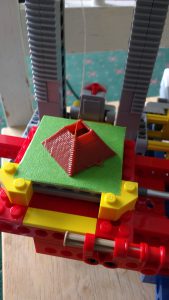
Producing Complex Structures on the EV3DPrinter
So, for the past few weeks I’ve been working on my build of the EV3DPrinter. I’ve had it printing various geometric shapes, “College” letters, and more recently I’ve been working on a complex shape – namely a castle:

Development
Since I’ve been programming my instance of the EV3DPrinter in EV3G I couldn’t realistically use G-Code as the string handling in EV3G isn’t up to the task. Instead I would do it some other way.
For years I’ve been using a very old X11 drawing package Tgif; this has the great advantage that its file format is text based, and object oriented – a perfect source of drawing data. I used this package to draw out my letters:

This worked perfectly as it was easy to convert the polygon path of each letter in to a simple set of coordinates for use in my code on the printer. I was however accidentally fortunate in that I’d aligned the letters to a grid, so could work out which one was which based on rows and then position along that row.
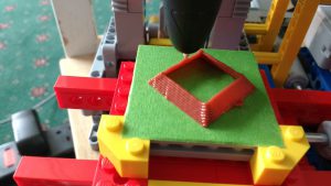
When it came to making the castle I figured I’d use the same program to develop each layer, and just write a new Perl program to parse the file into plot data. It was rather more complex than I’d thought. I had to design each and every layer of PLA, bar those layers that repeated, i.e. the first 5. So, first, I started off with just the base of the windows:
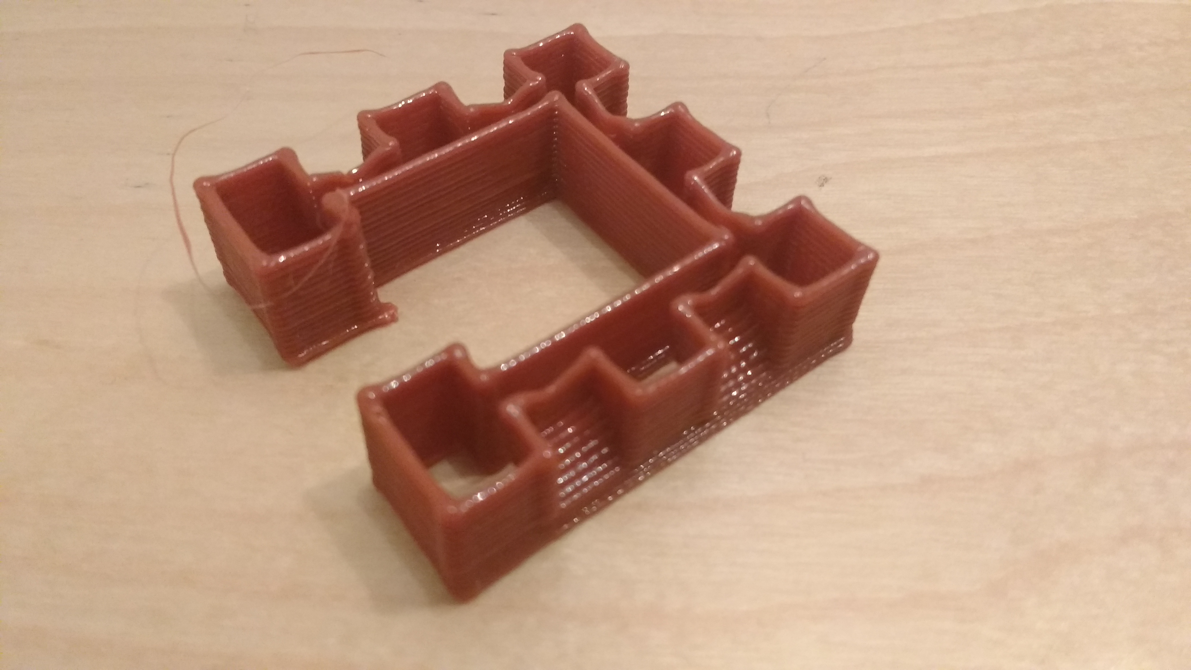
This took two goes as the first time I had the slope at the bottom at too shallow an angle, so they sagged badly. Next I worked my way up the walls:
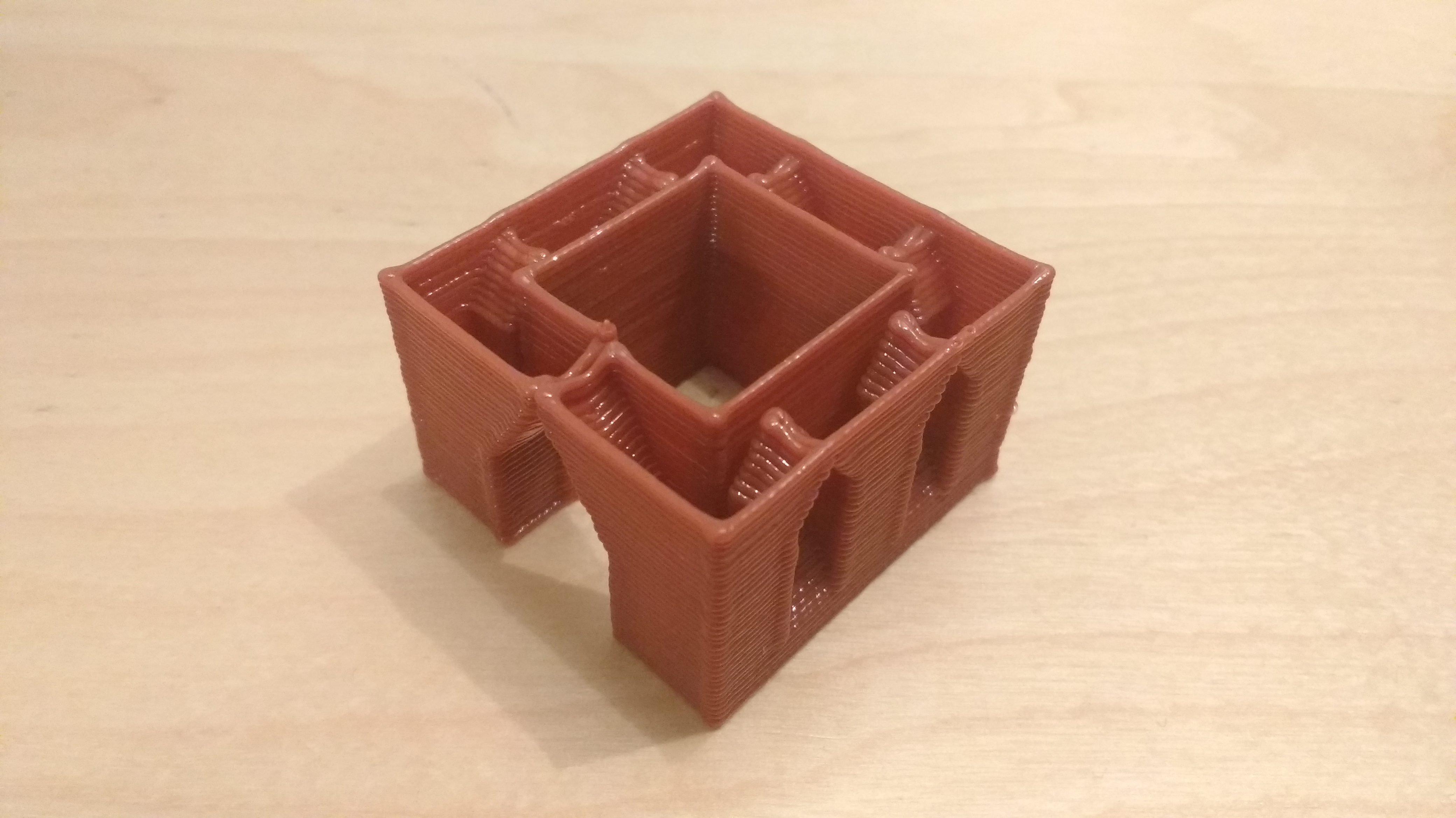
Eventually after some trial I got to the final castle.
Process – First Version
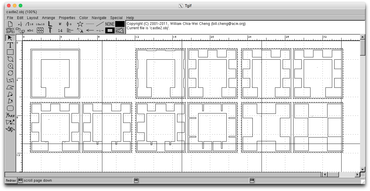
The luck I’d had with the letters couldn’t work with a complex object. I needed to be able to define a layer’s polygon, its position relative to the layer below and some form of order. The simple answer, for me, in Tgif was to have a bounding box, a text object with a number, and a polygon inside the bounding box, as below:
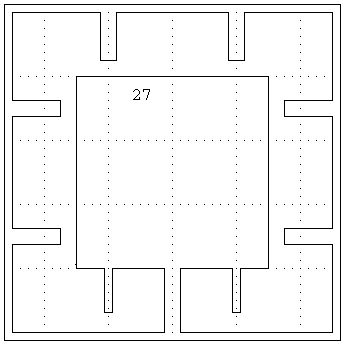
Layer 27, above, is closing up the tops of all the windows and the doorway, along with producing buttresses for the crenelations at the front. So here, there is the box, the number “27” and a polygon – the just visible arrow on the inside bottom left defines the end point of the path for that layer. The line width of the polygon defines how many layers are to be repeated for this path – 1 in this case.
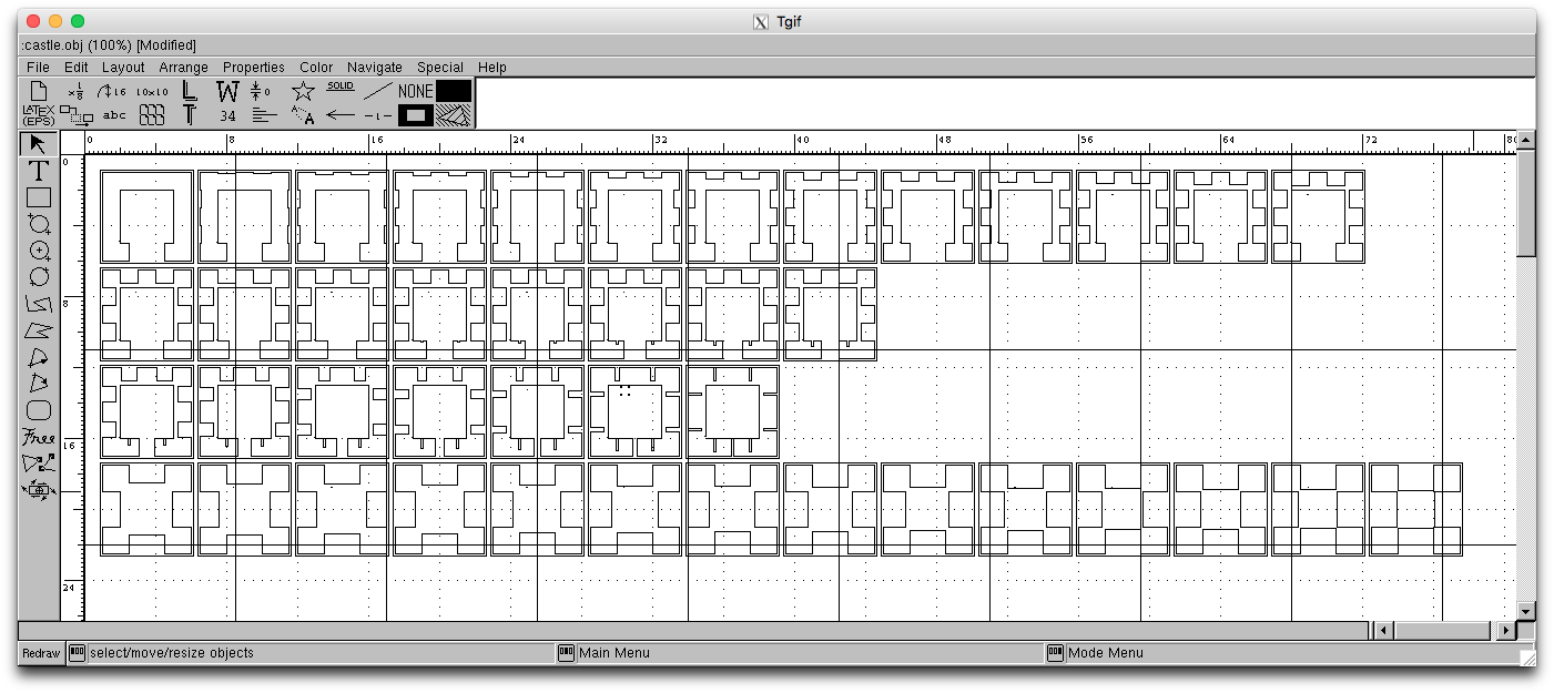
This was a time consuming process, which did work, but resulted in 42 layers. The final Tgif image looked as below:
Process – Second Version
Although the Tgif images, so far worked well, it was a lot of effort. Discussing with a colleague, he asked why I couldn’t define a start and an end and layer-by-layer go from one to the other. A bit of thinking and a new plan came to mind.
The same system of box, text, and polygon would be used by a way of linking a start and an end would be used – a simple dotted box would group two layers together. The layer numbers would define the start and end, and all layers between would be interpolated between the two polygons. Of course both polygons would need the same number of points, but that’s fine.
Some new coding, along with spotting a mistake in my first castle, and I get the new Tgif image of:
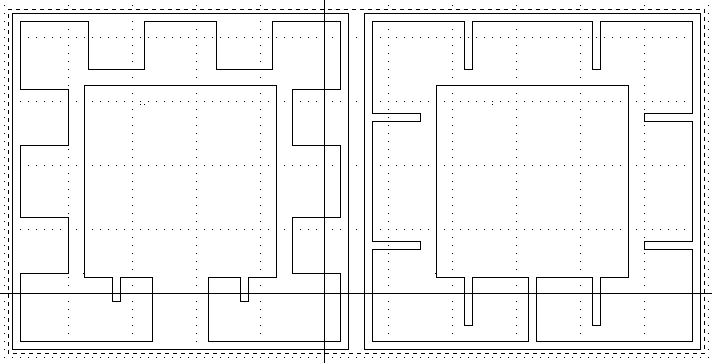
This is so much easier to manage. I’m now thinking on what to make next. I’ll be writing another program that will be able to read in multiple complex models and give a menu to select what to make. Once that’s done, I think I’ll be ready to publish my code – watch this space.
My First 3D Printer
I was rather impressed by Baz’s 3D LEGO printer when I got to see it at LW2017. So, I figured that when I had time I’d build it and have a go at coding it myself. I finally got all the parts this month and have built it up – albeit in different colours, and with a few minor structural changes.
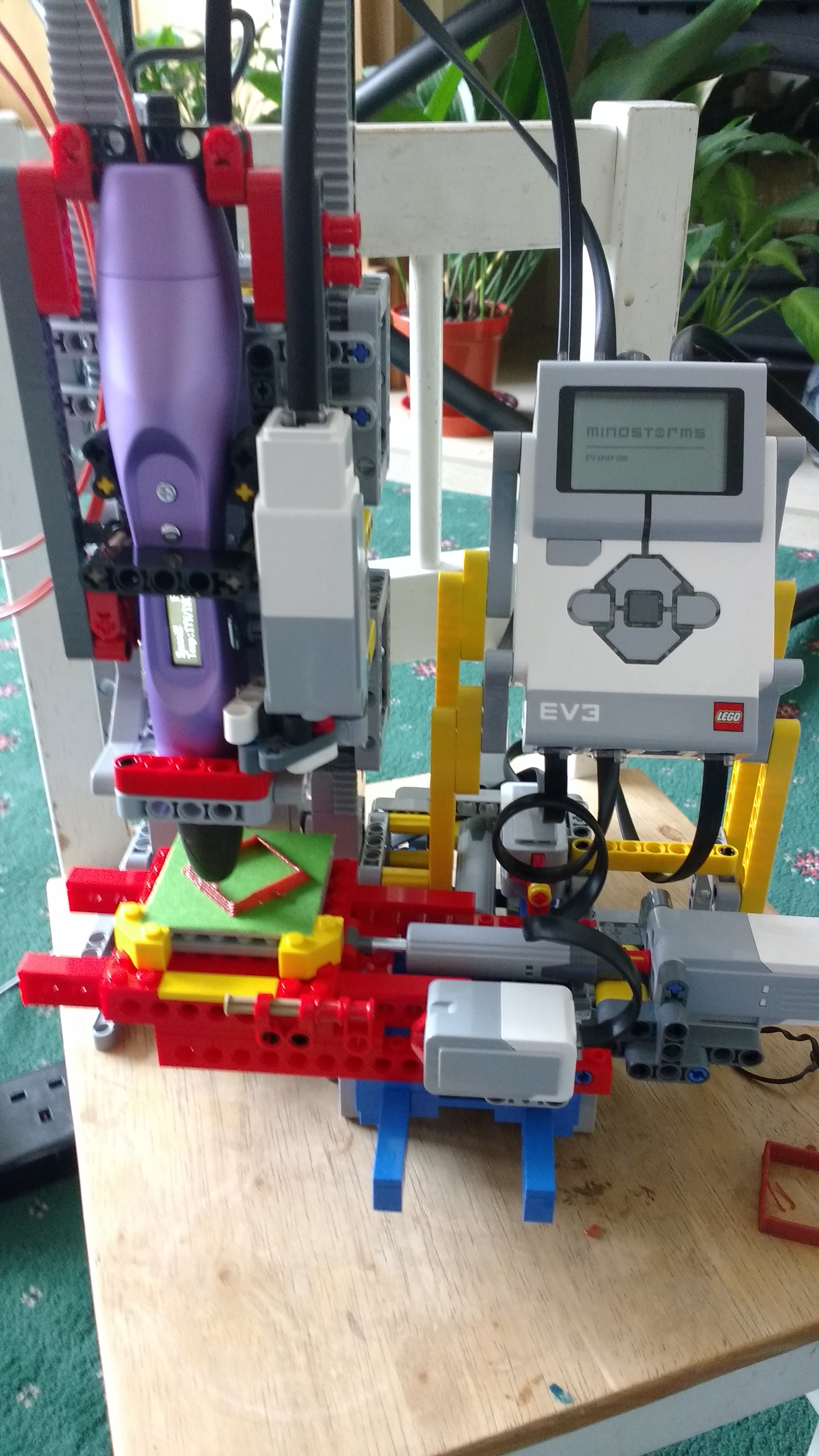
Today I got the code working for the first time! It’s not fully fledged, but it’s functional, so I’m going to post a link to what I have so that people can follow my progress. The link below points to this basic code:
http://www.jander.me.uk/LEGO/resources/EV3DPrinter_JN-v0-1.ev3
It will be expanded to do more things, such as simple geometric shapes/prisms/cones, and reading datafiles to print more complex structures. I doubt I’ll pursue the G-code system as that’s too complex to handle in EV3G.