I thought I’d put all the parts that I’ve done so far together, and animate it rotating in Studio. Here’s the video:
Tag: Bricksmith
Modelling my Loom
Ever since I started to show my LEGO® loom on this blog, Facebook and YouTube, I’ve had people ask me for build instructions. I’ve always said that I’d make them, and I will stick to that … but it’s a BIG task, and will take a long time.
Recently I’ve been making changes to the loom, so have been removing old parts and making new modules to replace them. What I decided to do as I went along was to actually model the parts I was removing, and to model the new parts as I went. This way I have the old parts for reference should I ever want to look back on them in the future, and the new parts have been modelled from the start. As time goes by I intend modelling the separate “modules” of the loom, and then build up a body of work of all the sections. I’ll still need to model the main framework of it, but that will come in time.
So, without further ado, here are the parts I’ve done so far.
Warp Thread Drum
This is the original warp thread winding drum. This was used at the back of the loom and stored the warp threads for feeding in to the loom. In my original build I used to have to wind the warp threads on, en masse, by hand. This suffered from a) being tedious, and b) the threads would wind on at different rates. Since the threads didn’t lie completely flat on top of each other, the drum would end up with different “thicknesses” of threads, resulting in some threads winding on faster than others – since C = 2πr. When the loom was running it’d pull all the threads through at the same rate. Due to the different winding thicknesses, this would either result in some threads getting very slack or, more commonly, some threads getting very very tight.
The LDraw model for this can be found at: http://jander.me.uk/LEGO/loom-parts/Warp%20Drum.ldr
Warp Thread Winding Gearbox
My solution to the differential winding of the warp drum, was to build a set of pinch rollers, that the warp threads went though, and a gearbox that drove the drum.
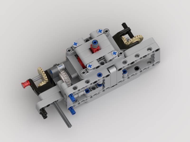
The pinch rollers would be in use during weaving, to provide a tension control between the back of the loom and the cloth take-up drum at the front. They would ensure that all the threads passed through the loom at the same speed.
The gearbox would be engaged when loading the warp drum. When engaged, the warp thread drum would rotate at a “surface speed” ever so slightly faster than the feed rate of the pinch rollers – the white clutch gear would deal with any mismatch in speeds. When weaving the gearbox would be flipped over to a gear with a friction pin, just to stop the warp drum free-spinning.
This appeared to work well, until the last time I loaded the loom. I was struggling with the threads getting caught up in the pinch rollers as they wound on. After watching it load, and thinking on it, it was the same differential speed problem as in the original loom, but in reverse. Now, as the threads wound on, they were winding on at different speeds due to not winding on flat. This was exacerbated by the use of the clutch gear. This meant that the warp drum rotated at the slowest speed, i.e. that of the thickest wound thread. The threads winding on to the thinner areas therefore became slacker, and would get caught on the pinch rollers, ultimately winding back inside them.
The LDraw model for the gearbox can be found at: http://jander.me.uk/LEGO/loom-parts/Warp%20Gearbox.ldr
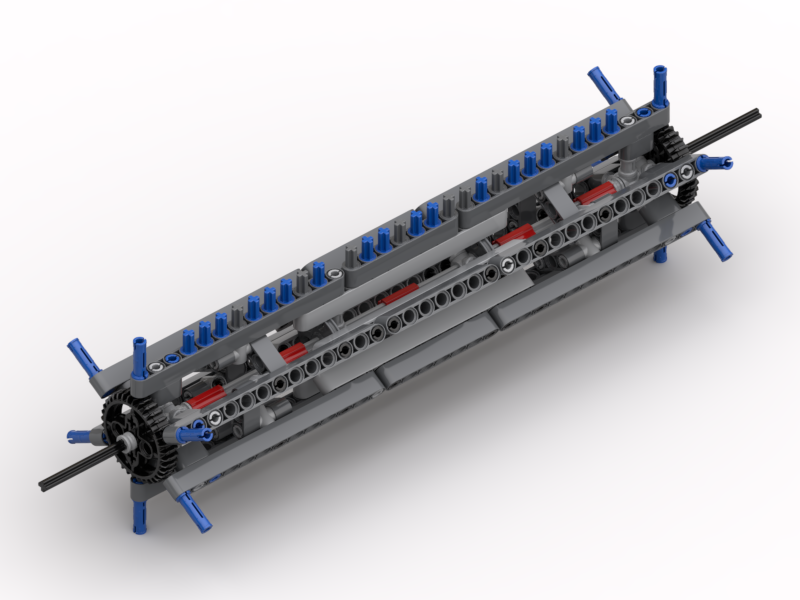
Bobbin Frame
My answer to the warp threads running at different speeds has been to make a frame that has 32 individual bobbins; one for each thread. I’ve yet to test that it actually works, but will do in the next few days. Now each thread can unwind at its own speed, and not be affected by its neighbour.
I’ve designed a frame that can hold them all, in the manner of a cartridge. This way it can be loaded up away from the loom if desired, and then clipped in to place.
Each bobbin has a black and dark grey disc, and a friction pin on one end and an axle on the other. Half of them have the friction pin on the black side, and the other half on the grey side. The friction pin is simply to stop the bobbin from free-spinning. All the bobbins will be wound in the same orientation with respect to the black/grey discs. This means that when they are all installed half will unwind clockwise, and the other half anti-clockwise. This is so that the threads don’t rub against each other (too much). The frame also has a set of long axles to act as thread separators. This is so that the threads don’t get twisted together, thus preventing them unwinding properly.
The LDraw model for the bobbin frame can be found at: http://jander.me.uk/LEGO/loom-parts/Bobbin%20Frame.ldr
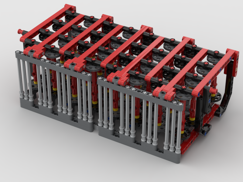
Bobbin Frame Support
To support the bobbin frame and to allow it to be easily removed and installed, a simple support structure was needed.
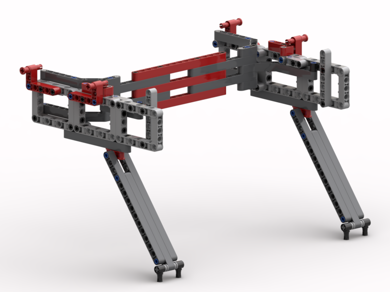
The red pin bushes at the top are used to lock the bobbin frame down on to the support. The bobbin frame itself has axle pins underneath that locate into the angled beams on top at the back. The whole thing is supported on the long angled arms, set at a 3:4:5 Pythagorean angle.
The LDraw model for the support can be found at: http://jander.me.uk/LEGO/loom-parts/Bobbin%20Frame%20Support.ldr
Bobbin Winder
Although I expect to wind the bobbins using my main winder, used for the weft threads, I wanted a winder mounted on the loom itself.
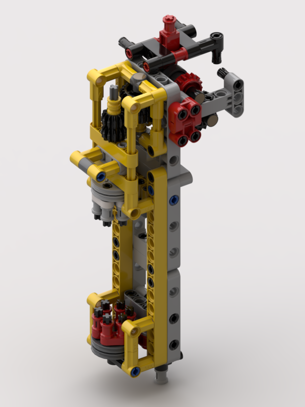
To achieve this a small winder has been made where there are two devices, dog teeth, that engage with the six holes on “wedge wheel” discs on the bobbins. The bottom one hinges out, and the top one slides up and is driven by the same motor that powers the pinch rollers. A single speed gearbox is used to engage/disengage the motor. This allows for it to be used when the loom is empty, and not powered when the loom is in operation.
The plan is to always wind bobbins with the black disc on the bottom, held by the red dog teeth. This will ensure that all the bobbins are wound in the same orientation.
The LDraw model for the support can be found at: http://jander.me.uk/LEGO/loom-parts/Bobbin%20Winder.ldr
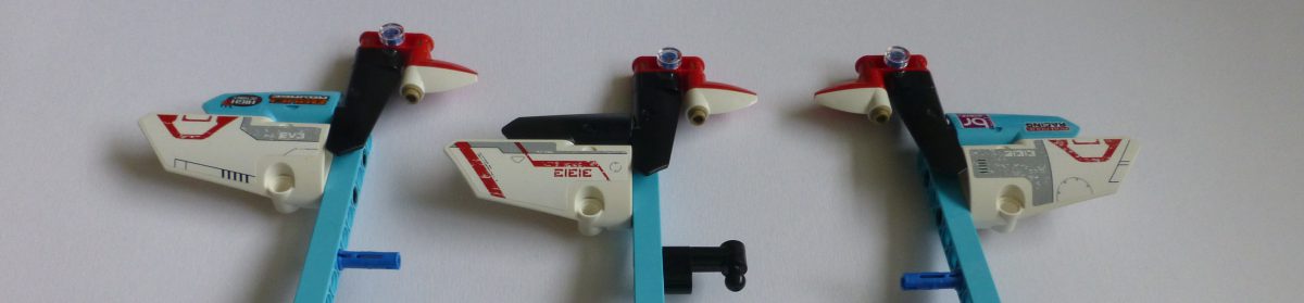
Weft Shuttle
Whilst I’ve been working on some of the issues, I thought I’d tackle the shuttle.
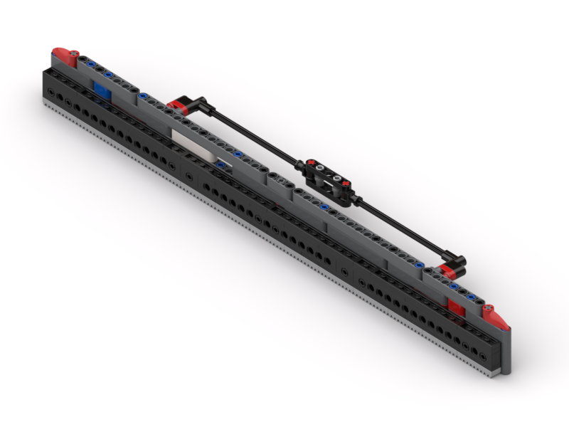
This has generally worked well, but now and again has got caught up on the threads as it’s passed through. This has been down the the “shed” (the hole inside the top and bottom warp threads being a little bit too small, and snagging the horizontal bar at the front. This bar is used to ensure that the weft comes out from the middle of the shuttle.
In my original design this bar sat 6L away from the shuttle. The supports that hold that bar in place, and the long bobbin between them, are now 5L and the bobbin sits at 2½L away. It may not make much difference; I have yet to test. If 5L is too short it is easy to modify it back to 6L.
The LDraw model for the shuttle can be found at: http://jander.me.uk/LEGO/loom-parts/Shuttle.ldr
Rendering
I build all my models in Bricksmith. I’ve used it for years, and know how to drive it. I’ve had a play with Stud.io recently, and still don’t (yet) get on with it. However, I really like the renderer that comes with it. So, I’ve been building my models in Bricksmith and using Eyesight, from Stud.io, to make the pictures seen in this article.
What’s Next?
Well, I still need to test that this all works. That’s something for this week, but I think Captain Marvel comes first 🙂
Bricksmith and Treads – Part 3
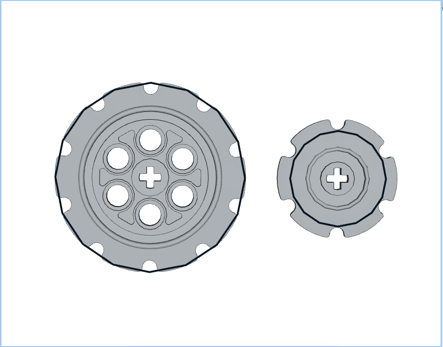
In this article I will finish discussing placing treads manually using Bricksmith. In Part 2 I referred to sprockets with the notch a the top:
These are much better in terms of placing the first tread as it will sit properly in the notch as it’s on an integer grid, unlike the 90˚ rotated version which is very slightly off that grid.
Technique
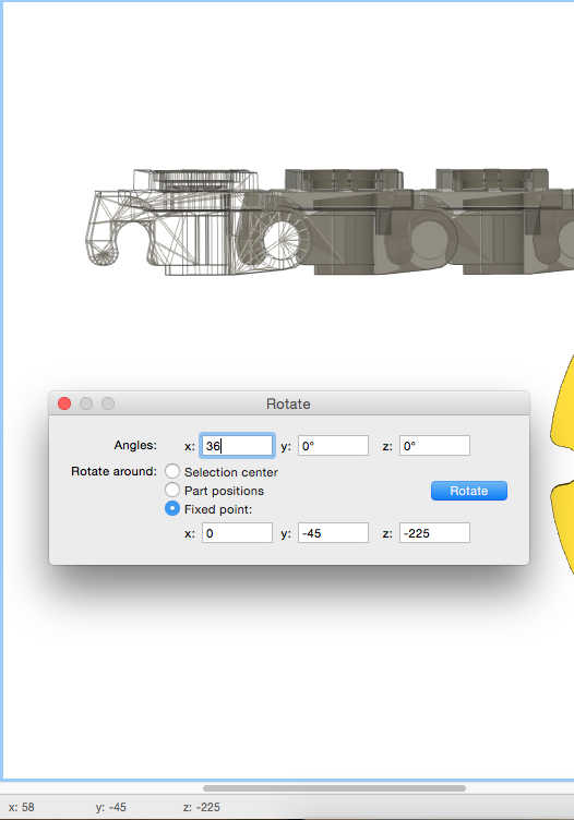
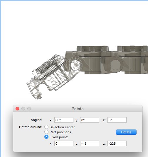
The technique is almost identical to that discussed in Part 2, but the first tread needs to be rotated by 18˚ after its initial placement:
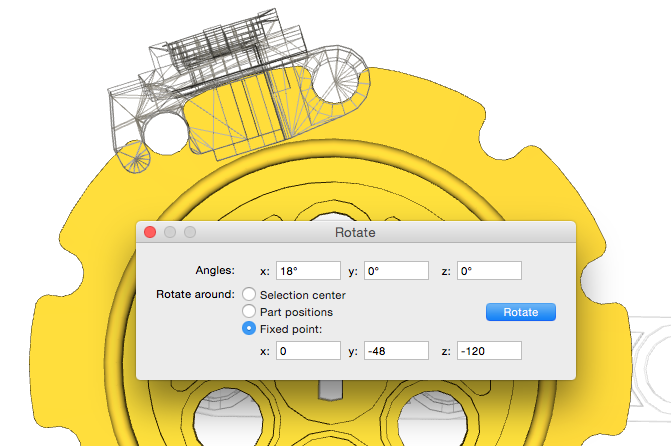
A point of interest is that the tread was rotated around a Y coordinate value of -48, i.e. a radius of 48 from the centre of the sprocket. This is different to the 50 used by LSynth as discussed in my previous post about my investigations in to LSynth:
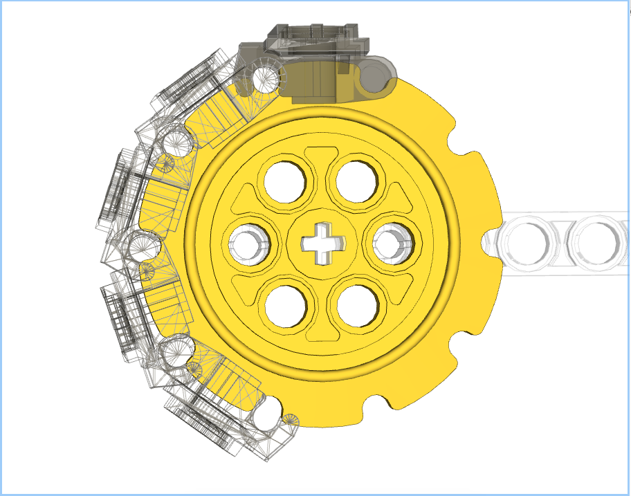
Once that first tread is in place and aligned, it is now a simple case of copying, pasting, and rotating as shown in part 2:

All done. One thing to note is that treads 2-5 have undergone two rotations each, but don’t appear to suffer any level of cumulative error. This is probably due to the first tread being rotated about its origin only. This results in the treads 2-5 only having one orientation rotation, and one position translation, thus reducing the errors.
This does look a lot of effort to do manually, but I’m used to it now and find it quick enough to do, and the results look good.
Bricksmith and Treads – Part 2
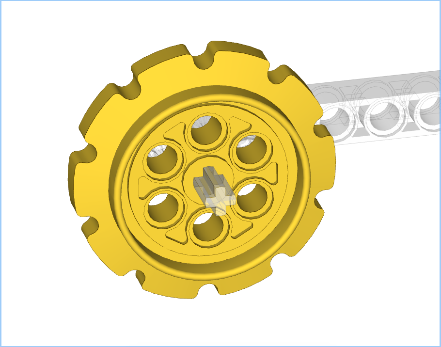
Sprocket Orientation
When building up a model in Bricksmith it’s important to consider the orientation of the sprockets. You’ll want them rotated such that the treads sit in the notches correctly. Generally the sprockets are going to end up in one of two orientations, 90˚ rotation between them:
The notch at the top is better as the treads will sit in the notch easily, whereas the notch at the side will require fine-grained movement to get the initial tread in place. For this particular post I will focus on the latter, i.e. notch at the side. Although this requires more initial set up the rotation of the treads is simpler. I will cover the other variant in a third post.
Rotation Controls
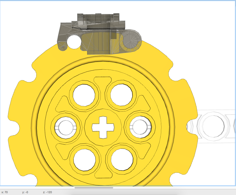
Since we’re wanting to place treads on the large sprocket, in my example, we’re going to want to rotate by 36˚. This is because there are 10 notches in the sprocket, so 360˚/10 = 36˚. The rotation controls are reachable from the Edit menu, and give a control box as below:

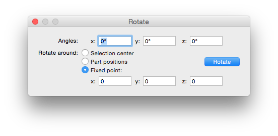
All of our rotations will be around a fixed point.
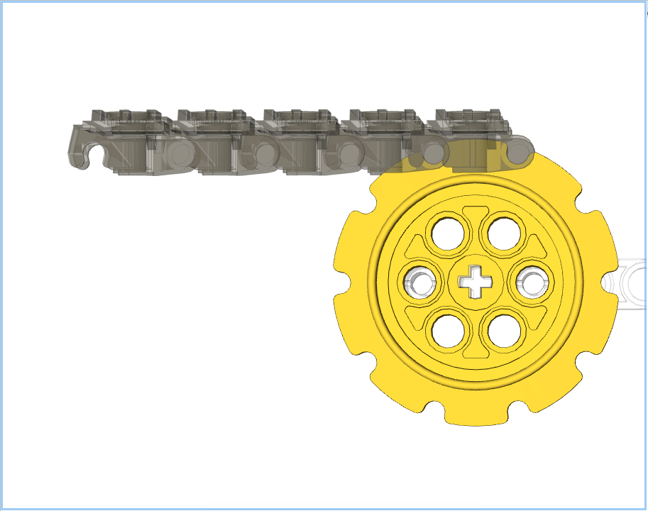
Initial Tread Placement
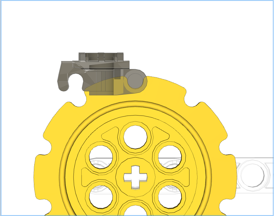
The first thing to do is align a single tread with the sprocket. This is relatively easy, but in this orientation will require the fine grid for movement. The first tread ought to look like:

How I Used to Do Treads – aka “Introducing Cumulative Error”
When I first started to model treads manually I’d start with a line of treads which I’d “bend” in to place:
I would then select the first tread and rotate it about its pin. The coordinates of this pin can be found by moving the pointer around over the pin and observing the coordinates shown at the bottom of the Bricksmith window:

You’ll notice that two of these values change as the pointer moves but the third, in this example the x value, doesn’t. The two that change are the coordinates of the line passing through the tread’s pin.
Next I select the the tread I have just rotated and its neighbour. I need to rotate both of them around the second tread’s pin. I know that the pins are 30 units apart, so I already know that the coordinates will be 0,-45,-195 without needing to check:

I now simply work my way back along the treads rotating around x=0,y=-45, and z=: -165 and -135. The result of this is:
This all used to make sense to me as the simplest way of doing this. However I started to notice small errors in placement. This can be seen in that the first tread doesn’t quite sit in its notches, a close up is below:
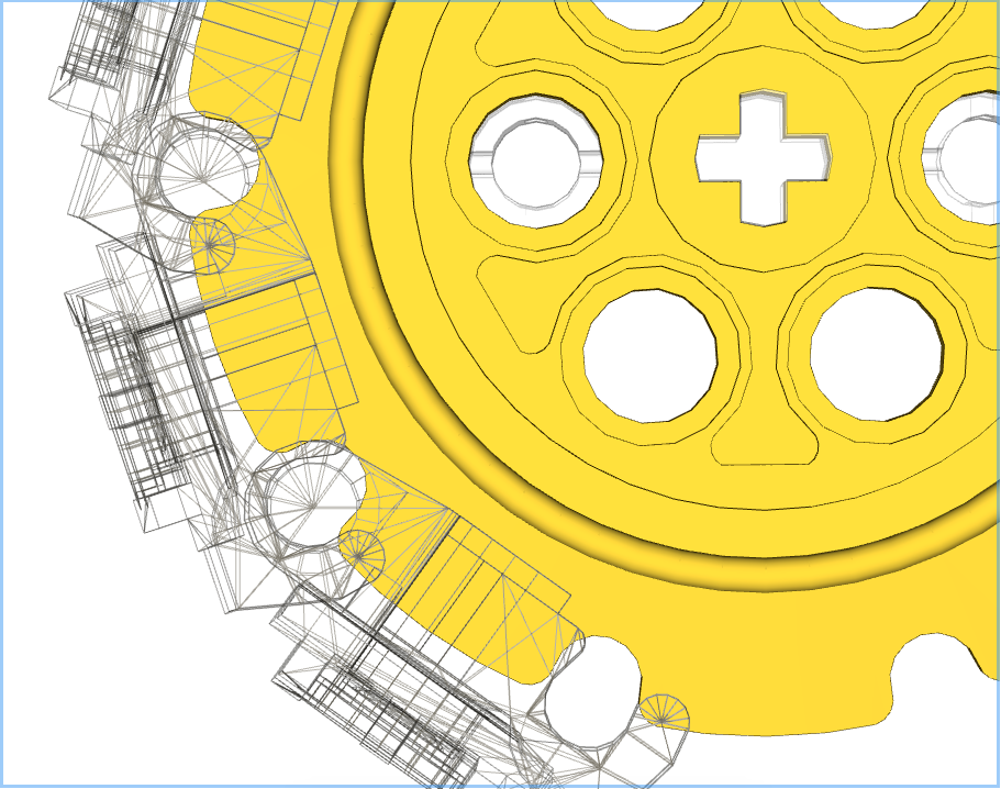
This is due to cumulative errors appearing. The first rotation is okay, but subsequent rotations slowly add errors to the placement. This first link has undergone 4 rotations around 4 different fixed points resulting in a small drift.
Being the perfectionist I am, this wasn’t acceptable, so back to the drawing board.
Individual Treads – aka “Doing it Right”
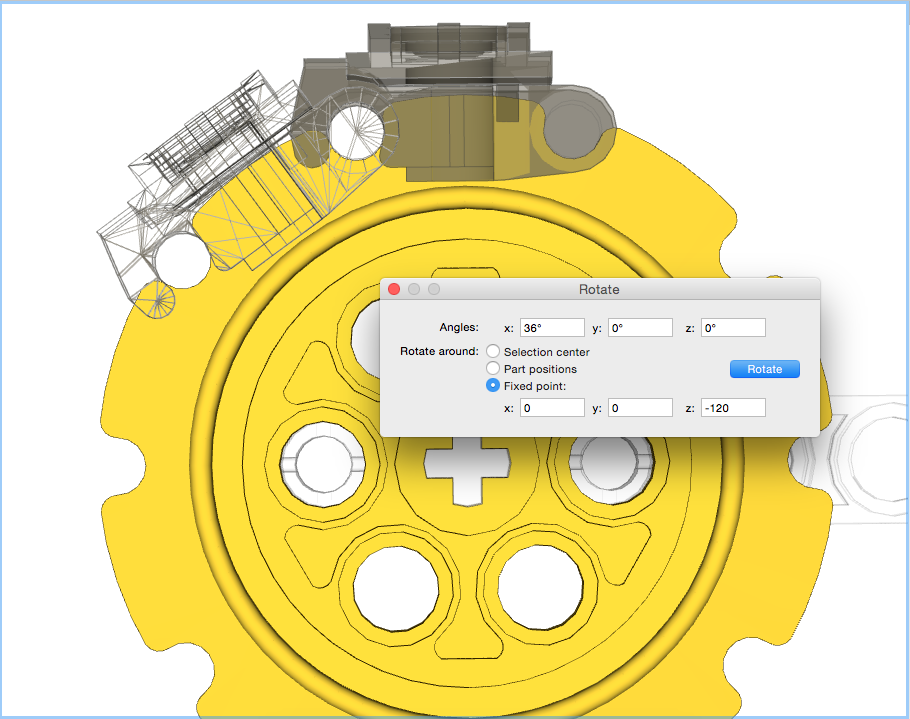
This time around we’ll only perform one rotation per tread, thus removing the cumulative errors. To achieve this copies of the top tread will be made, and placed in exactly the same spot, i.e. select tread, then cmd-C and cmd-V. This can just be seen in the image below with the wireframe inside the other tread:
This tread will now be rotated 36˚around the centre of the sprocket, not its pin:
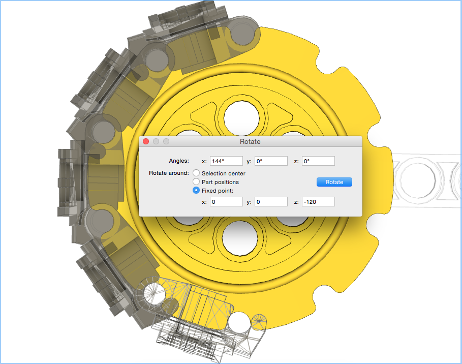
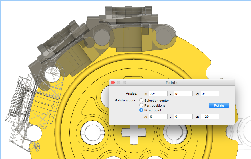
This will now be repeated, copying and pasting that top link, then rotating by 72˚, 108˚, and finally 144˚:
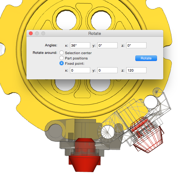
Treads with Rubber Feet.
One of the comments I made in Part 1 was that LSynth didn’t support treads with rubber feet. To do this the first tread will need a rubber foot located with it, and then those two together can be copied and rotated as above:
Completed Treads
Once the sprocket treads are in place, the top/bottom treads can be placed between the sprockets. For simplicity I copy and paste the initial tread placed on the sprocket:

LPub4 Parts List
Another comment I made in Part 1 is that the LSynth structure doesn’t show up in the parts list. Since the treads placed via the methods above are normal elements there will be a valid parts list shown both on the page and in any Bill of Materials:
I hope this makes sense. Feel free to leave comments if I need to make anything clearer.
Bricksmith and Treads – Part 1 “Not Using LSynth”
Bricksmith and Treads – Why they aren’t quite right.
When it comes to making my building instructions (BIs) I use Bricksmith for OSX. It’s a brilliant package for making models and even better it comes with LSynth integrated in to it. LSynth is excellent at doing flexible objects – most specifically the EV3 cables. It, however, doesn’t handle treads at all well; which is what this post is about. I’m not knocking LSynth in any way, but want to focus on how to get treads correct in Bricksmith, which unfortunately will be a manual process.
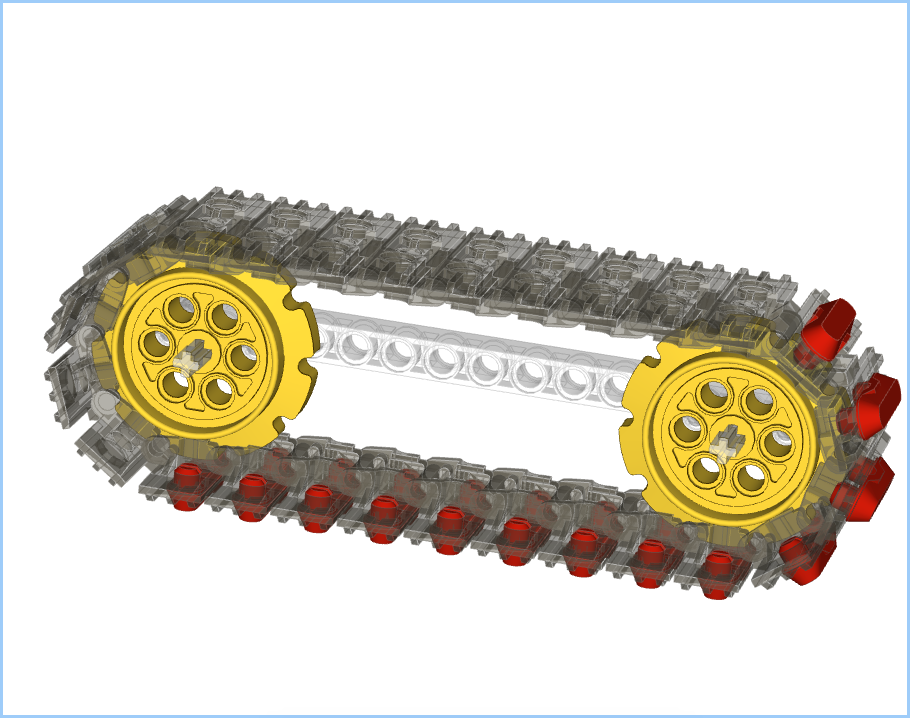
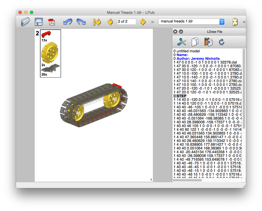
I figure that I ought to start by showing why I don’t use LSynth for my treads. Here’s a model with some treads:

This all looks good; I’ve used “trans black” and “trans clear” for parts so that we can see through them. This model ought to have 26 treads in it, however if one counts what’s in this model LSynth has put in 30 of them. This leads to the following issues:
Overlapping Treads
If you look at the picture below you can see that two of the treads are overlapping, and occupying most of the same space. This happens twice in the model, top left and bottom right:
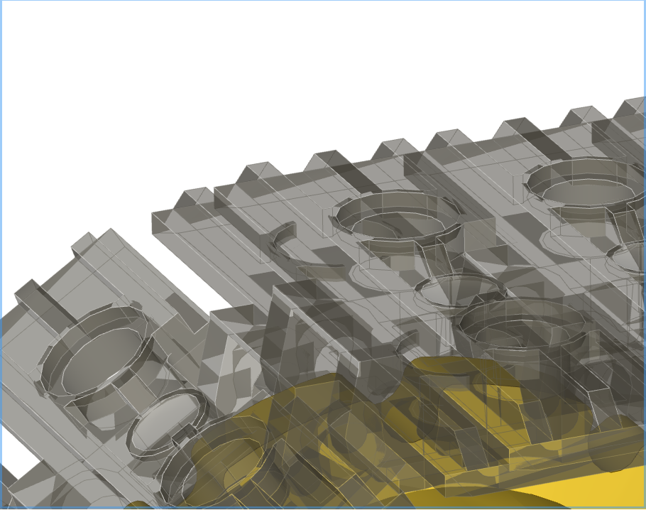
Compressed Treads
In the next picture it can be seen that the treads are far too close to each other. They are butted next to each other, but this results in the treads not joining at the pin / hooks which should be clear:
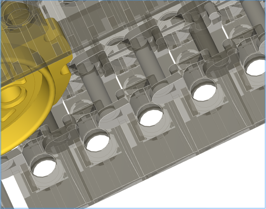
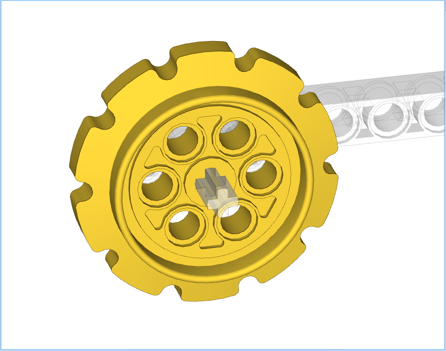
Misaligned Treads
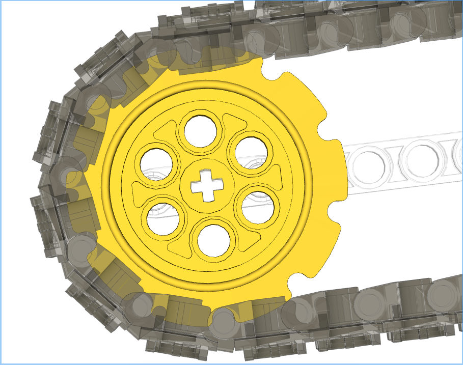
The next picture shows that the treads don’t align with the sprocket correctly. The bottom most tread almost has its pin in the sprocket’s indent, but not quite. As the links carry on around they progressively get further and further out of alignment. This is probably related to the earlier observation about the compressed treads.
No Rubber Feet
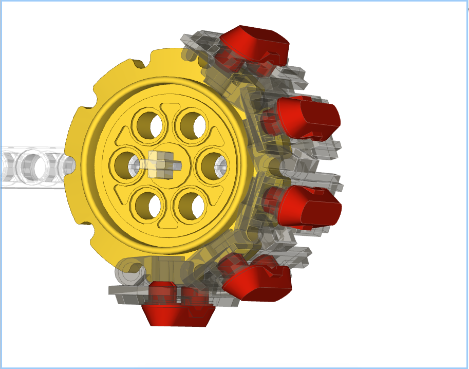
This isn’t really an LSynth problem as such, but there is no option for a band of treads with the red rubber feet, as below:

No Parts List
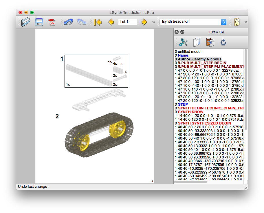
Again, this isn’t the fault of LSynth, but when an LSynth element is presented to LPub4 it doesn’t see it as a list of parts, so no list is shown. See the image below; there are parts for the beams and axles, but none for the sprockets or treads:
Conclusions
Again, I will state that LSynth is brilliant for EV3 cables, but from my experience it isn’t the right tool for putting treads in to BIs. I much prefer to do those manually, which I’ll cover in Part 2 of this series.
I’ll be making another blog post soon covering how to use Bricksmith and LSynth to put together EV3 cables, including coloured ends.